

TECHNICAL DOCUMENTATION
SSP 960143 – The 2015 Audi A3 Running Gear and Suspension System
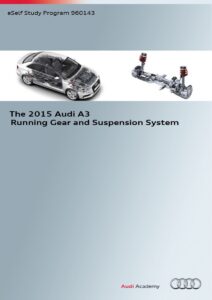
Loading PDF…
Read document text
eSelf Study Program 960143The 2015 Audi A3 Running Gear and Suspension System
Audi of America, LLC Service Training Created in the U.S.A. Created 11/2013 Course Number 960143 ©2013 Audi of America, LLC All rights reserved. Information contained in this manual is based on the latest information available at the time of printing and is subject to the copyright and other intellectual property rights of Audi of America, LLC., its affiliated companies and its licensors. All rights are reserved to make changes at any time without notice. No part of this document may be reproduced, stored in a retrieval system, or transmitted in any form or by any means, electronic, mechanical, photocopying, recording or otherwise, nor may these materials be modified or reposted to other sites without the prior expressed written permission of the publisher. All requests for permission to copy and redistribute information should be referred to Audi of America, LLC. Always check Technical Bulletins and the latest electronic service repair literature for information that may supersede any information included in this booklet.Revision 2: 12/20133
ContentsSuspension system - overall concept...................................................6 Suspension..........................................................................................7Overview ..................................................................................................................................................................... 7Axles and suspension alignment.........................................................8Front suspension ....................................................................................................................................................... 8 Four-link rear suspension ......................................................................................................................................... 9 Suspension alignment and set-up ..........................................................................................................................10Brake system.................................................................................... 12Overview ....................................................................................................................................................................12 Design and function .................................................................................................................................................16 Service operations ....................................................................................................................................................17 ESP overview .............................................................................................................................................................18 System components .................................................................................................................................................18 Service operations ....................................................................................................................................................20Steering system................................................................................ 21Overview ....................................................................................................................................................................21 Electro-mechanical steering ....................................................................................................................................21Audi magnetic ride........................................................................... 24Overview ....................................................................................................................................................................24 Service operations ....................................................................................................................................................27Adaptive cruise control (ACC)........................................................... 28Overview ....................................................................................................................................................................28 Design and function .................................................................................................................................................28 Operation and driver information ...........................................................................................................................28 Service and diagnostic operations ..........................................................................................................................28Wheels and tires............................................................................... 29Overview ....................................................................................................................................................................29 Tire Pressure Monitoring System ............................................................................................................................30eSelf Study Program......................................................................... 31 Knowledge Assessment................................................................... 324
This eSelf Study Program teaches a basic knowledge of the design and functions of new models, new automotive components or technologies. It is not a Repair Manual! All values given are intended as a guideline only. For maintenance and repair work, always refer to the current technical literature.NoteReference
Suspension system - overall conceptA major developmental goal for the suspension system of the Audi A3 was to achieve a high level of agility, sporty handling and high driving comfort without making any compromises to driving dynamics. Even it its basic configuration, the 2015 A3 affords a brandtypical driving experience and comfort with a strong emphasis on sporty attributes. The A3 offers a high level of driving enjoyment. This has been accomplished by using the proven concept of the MacPherson front suspension in combination with newly developed torsion beam and four link rear suspensions. The torsion beam version of the rear suspension is 33 lb (15 kg) lighter than an equivalent multi-link rear suspension in addition to having aerodynamic advantages. The use of the torsion beam rear suspension or the fourlink suspension is dependent on engine horsepower output. The A3 will also be available with all wheel drive in combination with the four-link rear suspension. An electronic damping control system based on the established Audi magnetic ride system will also be available as an option. A reduced weight electro-mechanical power steering system with speed dependent assistance (Servotronic) is standard equipment on the A3. A variable steering ratio is achieved through the special geometry of the rack and pinion system. A range of newly developed steering wheels extends from the conventional four-spoke wheel to the three-spoke multi-function sport steering wheel with leather trim and shift paddles. The 15 and 16 inch service brakes (engine dependent) are larger than those of the predecessor model and provide excellent braking capability relative to engine power output. A newly developed Continental Mk100 ESP system is being used for the first time by Audi.612_001a6
SuspensionOverviewThe following suspension system versions will be offered for the 2015 A3 sedan:Dynamic suspensionThe dynamic suspension system is standard in the 2015 Audi A3.612_002aSports suspensionThe sports suspension is optional. In models with sports suspension, ride height is 0.59 in (15 mm) lower than in models with the standard suspension. The S3 model will have its own version of the sport suspension featuring more sporty characteristics.612_002bSuspension system with electronic damping controlThis suspension system is currently available only on S3 models. It is based on the Audi magnetic ride system currently used in other Audi models.612_002cComponents of the 2015 Audi A3 suspension systems are also used by other Group brands. The production control numbers denoting the suspension type therefore deviate from those of suspension systems used exclusively by Audi.The production control numbers (PR numbers) are explained in the repair manual (ElsaWeb or ElsaPro). Under Repair Group 44 "Wheels, tires and suspension alignment".7
Axles and suspension alignmentFront suspensionA newly developed MacPherson strut front suspension is used on the 2015 A3. The kinematics give the vehicle sporty and dynamic qualities; agile handling, roll comfort, reduced vibration, low roll angle and good dynamic stability. Steering forces are transmitted directly to the swivel bearings to provide immediate steering response.Spring −− Steel spring with linear characteristicShock absorber −− Twin-tube shock absorber with additional polyurethane springAnti-roll bar −− Tubular anti-roll barsSwivel bearing −− Two versions are available depending on engine output −− 15“ wheels, steel swivel bearing −− 16/17“ wheels, aluminium swivel bearing612_003Joint −− Ball joint for connecting the wishbone and swivel bearingEngine/transmission mount −− Aluminium castingWishbone −− One-piece stamped steel designWheel bearing / wheel hub −− Third generation wheel bearing with integrated wheel hub8
Rear suspensionTorsion beam suspensionA newly developed torsion beam suspension system is used for front wheel drive models with the 2.0L TDI engine. This axle is used to accommodate the AdBlue tank necessary for the Diesel fuel system. Torsion is produced by a downwardfacing U profile. Due to the axle design, there is no need for an anti-roll bar. The axle locating bearings are highly rigid in the vehicle’s transverse direction to ensure a rapid build-up of lateral traction. Because the shock absorbers are in approximately the same position as in the multi-link rear suspension versions, only minor bodyshell modifications were required.Shock absorber −− Twin-tube shock absorber with additional polyurethane springSteel springs −− Steel spring with linear characteristicWheel bearings −− Third generation wheel bearing with integrated wheel hub −− Bolted to the axle612_004Bearing pedestal −− Stamped steel part −− Supports the rear axle at the bearing and is bolted to the vehicle bodyTorsion beam suspension −− Made of welded steel componentsBearing −− Rubber-metal bearing9
Four-link rear suspensionA four-link suspension for quattro and front wheel drive is used on vehicles with engine outputs of 114 hp (85 kW) and higher. This suspension will be standard equipment for gasoline powered vehicles in the North American region. The basis for the new development is the proven rear suspension from the predecessor model. The shock absorbers are now coupled to the spring link instead of to the wheel carrier. The anti-roll bars are also connected to the spring link. Spring travel has been increased in order to enhance comfort. The repositioning of the upper damper bearings has allowed the fuel tank filler design to be optimized. The weight of the axle has been significantly reduced by approximately 10 lb (4.5 kg) when compared to the predecessor model.Shock absorber −− Twin-tube shock absorber with additional polyurethane springSteel springs −− Steel springs with linear characteristicAnti-roll bar −− Tubular anti-roll barsTie rod −− Plastic componentWheel bearing / wheel hub −− Third generation wheel bearing with integrated wheel hub −− Adopted from predecessor model for front wheel drive −− New part for quattro driveSpring link −− Made of hightensile steelUpper track control arm −− Made of steel612_005Trailing arm −− Stamped steel partWheel carrier −− Steel casting for front wheel drive −− Aluminium casting for quattro driveRear sub-frame −− Made of steelBearing pedestal −− Stamped steel partBearing −− Rubber metal bearingTrack link −− Made of steel10
Suspension alignment and set-upThe left and right toe-in angles on the front axle can be adjusted separately by changing the length of the track rods. The camber can be balanced (centered) within narrow limits by moving the sub-frame transversely. Individual toe and camber angles can be adjusted on the four-link rear suspension. There are no adjustments on the torsion beam rear suspension.Toe adjustment at the spring link/subframe attachment point (not shown).Toe adjustmentCamber adjustment612_00611
Brake systemOverviewThe brake system of the 2015 A3 is a logical progression of its predecessor. It is the first Audi to be equipped with the Continental ESP MK100 brake system. At the start of production, 15 inch and 16 inch systems will be used depending on engine output. Around mid-year, 2014 the Audi S3 will come standard with 17 inch brakes. Pistons with larger diameters than those of the predecessor model are used on all models. The electro-mechanical parking brake (EPB) is now used on the 2015 A3. The brake servo and pedal assembly are newly designed.ESP MK 100 by Continental612_001a15”, 16” or 17” brakesTandem master brake cylinder with single 10“ or 11“ brake servo15" or 17” rear wheel brakes with electro-mechanical parking brake (EPB)12
Front wheel brakesEngine type Minimum wheel size Brake type Number of pistons Piston diameter Brake disc diameter R4 2.0 TDI 150 hp (111 kW) 15“ PC57-25/14 15“ TRW 1 2.24 in (57 mm) 11.33 in (288 mm) R4 1.8 TFSI 170 hp (125 kW) R4 2.0 TFSI 220 hp (162 kW) 16“ PC57-25/14 16“ TRW 1 2.24 in (57 mm) 12.28 in (312 mm) R4 2.0 TFSI 285 hp (206 kW) 17“ C60-30/13 17“ TRW 1 2.36 in (60 mm) 13.38 in (340 mm)612_02713
Rear wheel brakesEngine type Minimum wheel size Brake type Number of pistons Piston diameter Brake disc diameter R4 1.8 TFSI 170 hp (125 kW) R4 2.0 TDI 150 hp (112 kW) 15“ FNc-M38-1510 TMD Continental 1 1.49 in (38 mm) 10.70 in (272 mm) R4 2.0 TFSI 220 hp (162 kW) R4 2.0 TFSI 285 hp (210kW) 17“ FNc-M42-1722 TMD Continental 1 1.65 in (42 mm) 12.20 in (310 mm)612_02814
Brake servo, master brake cylinder, pedal assembly10” or 11” single diaphragm brake servos are used on all left hand drive A3 models. The size is dependent on engine type. The brake servo is newly developed and is considerably lighter than the predecessor. The weight reduction was achieved by using high tensile steel for the outer shells and revised contours. Brake pressure build-up is based on a single rate characteristic.612_029The pedal assembly of the 2015 A3 is a new design. The brake and accelerator pedals are suspended from a common plastic bearing pedestal. This was done to reduce weight.Plastic bearing pedestal612_030Electro-mechanical parking brake (EPB)An electro-mechanical parking brake system is used on the A3 model line for the first time. The system and software is supplied by Continental.612_03115
Design and functionLeft and Right Parking Brake Motors V282 and V283 are different from the TRW components used in previous Audi models. Gear reduction is provided by a two-step worm drive assembly. The required self-locking effect is produced in the second step. The brake caliper spindle is inserted into the spur gear of the second gear step when assembling the parking brake motor. The spindle and spur gear are connected by internal and external Torx® profiles. The spindle is a component part of the ball screw and is mounted in the brake caliper. It applies pressure to the inner face of the brake piston via the spindle nut. The spur gear, driven by the electric motor, transmits the rotational movement to the spindle. The thrust element moves lengthwise when the spindle rotates. Depending on the direction of rotation, the thrust element moves towards the base of the brake piston or in the opposite direction. As a result, the brake piston is pressed against the brake pad (braking position) or moved away by the brake pad (release position). The brake and release operations are controlled in the same way as in the EPB systems used in other Audi models. Deactivation of the maximum clamping force of approximately 17.5 kN is controlled by applying up to approximately 12A of electrical current. A temperature model in the ABS/ESP Control Module calculates the cooling of the brake discs and pads when the vehicle is parked and, if necessary, tightens the parking brake up to three times by briefly activating the electric motors.Brake caliper spindle engagementWorm gear assembly of second gear step Worm gear assembly of first gear stepElectric motor612_032Brake pistonBrake piston in release positionBrake discThrust piece (spindle nut)Ball screwSpur gear of second gear stepSpindle612_033Brake padBrake piston in applied position612_03416
Service operationsThe thickness of the outer brake pads on all wheels can also be checked using measuring pin T40139A. A brake pad wear indicator is installed on the right wheel brake of the front axle on the 2015 A3. The contact is attached to the inner brake pad.612_035Brake padMeasuring pinThe control software for the EPB is integrated in the ABS/ESP Control Module. The service functions of the EPB are accessed through Address Word 03. The Address Word normally used for EPB (053) is unassigned. To replace the rear brake pads, you must initiate the corresponding Test Plan using the VAS Scan Tool. The parking brake is then opened as far as possible so that the brake pads can be replaced. After replacing the brake pads, the parking brake is closed and the required clearance between the brake pad and brake disc is set automatically. When installing the new brake pads, care must be taken to ensure that the locking pins on the back plates engage the brake piston pockets.612_031!17WarningDue to the modified design of the EPB parking brake motors, the self-locking effect is no longer provided by the spindle in the brake caliper, but rather by the second gear step in the parking brake motor. As a consequence, the parking brake is released as soon as the parking brake motor is detached from the brake caliper. To prevent the vehicle from rolling away during service, it is important that the vehicle is be secured before disassembling the parking brake motors. The parking brake motors should only be removed on a level surface with the remaining wheels blocked or on a vehicle lift.
ESP overviewThe Continental ESP MK 100 system is used in the Audi A3. This ESP system is a more advanced version of the ESP MK 60 system used in the predecessor model, both in terms of its hardware and software. The ESP unit is mounted on the right side long member in the engine compartment.System componentsABS/ESP Control Module J104Rotation Rate Sensor G202, Transverse Acceleration Sensor G200 and Longitudinal Acceleration Sensor G251 have been integrated with ABS/ESP Control Module J104. This eliminates the use of ESP Sensor Unit G419 found in the predecessor model. The control software for the EPB has been integrated in ABS/ESP Control Module J104. The control module performance has been enhanced by using new electronic components and more advanced software. The ABS/ESP communicates via the Suspension CAN bus.ABS/ESP Control Module J104Hydraulic unitHydraulic unitTwo versions of the hydraulic unit are used dependent on the installation of Adaptive cruise control (ACC). A hydraulic unit with special noise reduction features and a reinforced pump are used on vehicles with ACC.612_037Continental ESP MK 10018
ABS Wheel Speed Sensors G44 - G47Active wheel speed sensors are used on the 2015 Audi A3. There are two configurations for the sensors at the rear axle. If the vehicle is equipped with Audi park assist and/or ACC, the sensors will additionally record the direction of rotation of the wheels and the clearance between the sensor wheel and sensor.612_038System functionsThe 2015 A3 has the same ESP system functions as its predecessor model. An additional new feature is the active brake pressure build-up for the ACC function and Audi pre-sense front brake operations. If the system identifies a situation of impending vehicle instability based on the relevant signals, the brake system is pre-filled. A moderate build-up of brake pressure is initiated by the activation of the ESP pump. The purpose is to eliminate the brake pad / disc clearance which reduces the reaction time during subsequent braking manoeuvres. The brakes are also pre-filled if an emergency braking operation is initiated by the driver. During an emergency braking maneouver, drivers usually take their foot of the accelerator pedal very quickly and apply full braking. The movement of the accelerator pedal is evaluated in these situations. The Hill Start Assist function is optional with the A3 for the first time in this model series. Another new feature is the post collision brake assist function. This function reduces the danger of skidding and further collisions during an accident by automatically initiating a vehicle braking operation. The function is active during head-on, side and rear collisions if a predetermined deployment threshold is exceeded. If the threshold is exceeded, the Airbag Control Module instructs the ABS/ESP Control Module to brake the vehicle via a bus message. The ABS/ESP system then builds up brake pressure at all four wheels. There are several conditions for activation. First, the vehicle must be travelling at a speed greater than 6.2 mph (10 kph). Further, the ESP system, hydraulic brake system, and the on-board power supply must all remain intact during the collision. Automatic braking is deactivated during the following driver actions:• The driver depresses the accelerator pedal. • The driver brakes by applying a brake pressure higher than thebrake pressure applied by the system.If an ESP system fault has occurred, the post collision brake assist function will not be available.Reference The actions implemented by the ABS/ESP Control Module for Audi pre-sense and pre-sense front are described in eSelf-Study Program 990143, The 2015 Audi A3 Introduction.Operation and driver informationIf the ESP button on the instrument panel is pressed for less than three seconds, Sport mode is activated. The TCS function is simultaneously deactivated. Stabilizing ESP inputs are not made until much higher wheel slip values. If the ESP button is pressed for longer than three seconds, TCS and ESP are both deactivated.612_01419
Service operationsThe ABS Control Module and hydraulic unit can be separated for repair. The same condition applies here as to the predecessor model: control modules can be replaced individually but the entire ABS/ESP unit must be replaced if hydraulic units are faulty. After replacing an ABS/ESP Control Module, it must be encoded online. Steering Angle Sensor G85 must be calibrated and initialized through Power Steering Control Module J500. Several basic settings must then be configured. At the same time, the brake pressure, longitudinal acceleration, transverse acceleration and yaw rate senders are calibrated. Since the control software for the electro-mechanical parking brake is a function of ABS/ESP Control Module J104, a function check is performed on the EPB by twice opening and closing the parking brake. The ESP intake and isolating valves are subsequently calibrated, as previously in the predecessor model equipped with MK 60 EC. The TPMS is also enabled at this time. The concluding actuator diagnostics ensure that the hydraulic lines are correctly connected to the hydraulic unit and the ESP system is tested for proper function.Special tool VAS 6613Wrist band ESD table mat with equipotential bonding612_040!NoteTo avoid damaging electronic components by electrostatic discharge, the control module and hydraulic unit must always be removed/assembled using Special tool VAS 6613.20
Steering systemOverviewThe steering system concept for the 2015 A3 has been adopted from the predecessor model. This includes the electro-mechanical steering system and, a mechanically adjustable steering column. A progressive steering system will be offered as an option in combination with the sports suspension at a later date.Various steering wheels are used based on vehicle optionsMechanically adjustable safety steering column with stepless adjustment 2.3 in (60 mm) longitudinally 1.9 in (50 mm) verticallyElectro-mechanical steering with Servotronic function is standard equipment612_017Electro-mechanical steeringDesign and functionThe functional principle of the steering system has been adopted unchanged from the predecessor model. Torque assistance is provided by a second steering pinion which is driven by an electric motor. A torque sensor determines the steering torque applied by the driver. The electronic control module determines the required torque assistance in dependence on steering torque, vehicle speed, steering angle, steering speed and other input variables. A major modification compared to the predecessor model is the use of a synchronous motor in place of an asynchronous motor. By making this modification and by redesigning the geometry of the steering housing, the overall weight of the steering unit has been reduced by approximately 5.5 lb (2.5 kg). The position of the electric motor's rotor is identified by a rotor speed sender built into the motor. This sender has the same functional principle as the sender used in the predecessor model. A temperature sensor integrated in the control module measures the output stage temperature. If a predetermined limit is exceeded, power steering assistance is incrementally reduced. If a system fault is detected, power steering assistance is deactivated. System faults are indicated to the driver visually by a yellow or red indicator lamp and audibly by acoustic signals.Reference For detailed information on the design and function of the electro-mechanical steering system, refer to eSelf-Study Program 993503, The 2006 Audi A3 Running Gear.21
EPS pinionSteering Motor Speed Sensor G577Steering angle sensor G85 Steering torque sensor G269612_018Synchronous Electro-mechanical Power Steering Motor V187Power Steering Control Module J500Steering pinionProgressive steering(not available at model introduction)Progressive steering is provided by a variable steering ratio. A special rack gearing geometry is used to ensure that the steering ratio is variable as a function of steering angle. A progressive steering system will be offered as an option in combination with the sports suspension at a later date.612_019RackSteering pinionSteering ratioThe steering ratio is at its highest when driving in a straight line and during minor steering inputs near the center position. The immediate vehicle response to steering inputs conveys a sporty and direct steering feel to the driver. At medium steering angles (for example, when driving on winding country roads), the ratio is still large enough to create a dynamic steering feel and reduce the need for drivers to move their hands on the steering wheel.Steering angle612_020At large steering angles (for example, in inner-city areas or when parking), the steering ratio is reduced to minimize steering effort for the driver.22
Service/diagnostic operationsThe electro-mechanical steering system components described here have self-diagnostic capability.1. Special system status indication Yellow warning lamp active:The yellow warning lamp is activated in the following cases:• The end stops have not been programmed or SteeringAngle Sensor G85 is not calibrated. In this case, the fault is registered and power steering assistance is reduced to approximately 60%. Calibrating the steering angle sensor deactivates the warning lamp again and automatically clears the DTC from the fault memory.612_023• A system malfunction has occurred: in these cases, anadditional text message appears in the DIS and the fault is registered. The vehicle can be driven to the nearest repair center, but with reduced steering assistance.Red warning lamp active:The red warning lamp is activated in the following cases:• A system test is run internally directly after switchingthe ignition ON, during which the warning lamp is briefly activated for test purposes. If the system is fault-free, the warning lamp goes out again after a few seconds. In vehicles with the optional advanced key, the yellow warning lamp for testing the electrical steering lock system is briefly activated before the red warning lamp.612_024• If the warning lamp is continuously lit, it means that asystem fault has been detected. In these cases, an additional text message appears in the DIS and the fault is registered. It is no longer possible to continue driving.2. Removing, installing and replacing system components and follow-up workThere is no provision for the replacement of individual components. In the event of a fault, the complete steering unit must always be replaced. After installation, Steering Angle Sensor G85 must be calibrated before Power Steering Control Module J500 is encoded. The steering end stops are also stored during this calibration procedure. The power steering map required for the vehicle is activated after the calibration is made. The characteristic maps are selected depending on front axle load and vehicle weight.Power steering Control Module J500612_02523
Audi magnetic rideOverviewA newly developed Audi magnetic ride system will be optionally available on the 2015 Audi S3 at a later date. The system is operated using Audi drive select. Three different suspension set-ups ranging from sporty to comfortable can be selected.Design and functionThe system has the same functional principle as the systems currently being used in the, TT and R8 models. The system components and the key new design and functional features are described below.Driving Profile Selection Switch Module E592Damping Adjustment Indicator Lamp K189Damping Adjustment Valves, left front N336 right front N337612_007aVehicle level sender, rear right G77 rear left G76Damping Adjustment Valves, left rear N338 right rear N339Electronic Damping Control Module J250Level Control Sensors, right front G289 left front G7824
Damping Adjustment Valves N336-339As with the systems used on current Audi models, singletube shock absorbers are also used on the 2015 Audi S3. The shock absorbers essentially differ from those of the predecessor model in respect to the new features on the 2015 Audi A3 below. The damper pistons have two separate magnetic coils. These allow the same magnetic flow to be achieved using smaller iron cross-sections, thereby reducing eddy current losses. This improves the magnetic properties of the coils and thus allows damping forces to be built up more quickly. The result is enhanced comfort. Single-conductor technology was used in the shock absorbers on the predecessor model. Electric current was fed to the magnetic coil in the piston through a wire, while the piston and piston rod acted as the ground circuit. Twinconductor technology is used on the 2015 S3. With this system, the ground circuit is a separate wire. This eliminates the need for extensive electrical insulation and simplifies system diagnostics. The damper seal has also been redesigned. The result is better low temperature stability and resistance to ingress of dirt from the exterior. The diameter of the rear axle shock absorbers has been reduced from 1.8 in (46 mm) to 1.4 in (36 mm) when compared to the predecessor model which provides a weight saving benefit.Optimized sealsDamper pistons with twin magnetic coilsTwo separate lines for electrical current supply and return612_008Electronic Damping Control Module J250Electronic Damping Control Module J250 has also been upgraded. A new processor provides increased speed while the internal memory has been substantially expanded. A new security concept has been adapted to enhance system diagnostics. The frequency of the pulse width modulated signal used to activate the shock absorbers has been increased to 31 kHz. This reduces the variation in magnetic forces and damping forces and thereby improves acoustics. The damper is not activated when the vehicle is stationary (speed signal = 0). Faster force reduction and more precise and comfortable control are achieved by a new switching concept for the deactivation path. In addition, various new requirements were met, such as a reduction in static current consumption. The control module is installed under the right front seat.612_00925
Level Control System Sensors G76-78, G289Four vehicle level senders are also used in the Audi S3. They have the same function as the senders of the current A4. They were adapted to the installation space available in the S3 by making geometric modifications.612_010Operation and driver informationSystem settings are made through Audi drive select by pressing the corresponding button in the toolbar. The first push of the button displays the mode currently set in the Driver Information System. This display remains active for six seconds. If the button is pressed again during this time, the next mode is selected in the following order:• comfort - auto - dynamic - individual612_011In vehicles with NAV, settings can optionally be made in the CAR menu using the turn-push button of the MMI system. In vehicles with the multifunction steering wheel, the programmable button can used as an operating element for Audi drive select.612_012a612_01326
Service operationsAudi magnetic ride has self-diagnostic capability. If system faults are detected, the warning lamp in the instrument cluster and the text output in the Driver Information System are activated. The damping control system is modified accordingly or deactivated completely depending on the severity of the fault. ESP is activated automatically when required. The control module be accessed after moving the front right seat back as far as it will go. It is located under a cover on the carpet. The control module is encoded only when writing the vehicle data record. After encoding has been completed, the “Program default suspension height” can be performed using the VAS Scan Tool. The “Program default suspension height” Test Plan must always be performed after reinstalling/replacing:• Electronic Damping Control Module J250 • a shock absorber (or multiple shock absorbers) • a vehicle level sensor612_01527
Adaptive cruise control (ACC)OverviewACC is available as an option for the first time in the A3 model line. The customer can choose between two options:Driver Assistance Systems Camera R242• The stand-alone ACC option operates over a speed range of0 mph - 94 mph ( 0 km/h - 150 km/h) on vehicles equipped with an automatic transmission. (Note: the 2015 A3 in North America will only be available with an automatic transmission at the time of launch)• If the vehicle has the optional “driver assistancepackage” which includes ACC, the system operates with an extended speed range of 0 mph - 125 mph (0 km/h - 200 km/h) for vehicles with an automatic transmission. This optional package also includes Driver Assistance Systems Camera R242.There is no difference between the systems in terms of their design and function.Adaptive Cruise Control Sensor G259 and Distance Regulation Control Module J428612_041Design and functionRadar sensors with four transmitter and receiver units are used on 2015 A3. The ACC system generally functions the same as systems currently in use on other Audi models. The A3 has the ACC stop and go function if the vehicle is equipped with an automatic transmission. The pre-warning and braking intervention functions used in current Audi models under the designation “braking guard” are now included in Audi pre-sense. A new safety function for the A3 model automatically brakes the vehicle in the event of an impending collision at speeds below 19 mph (30 km/h). This function (post collision brake assist) is also included in Audi pre-sense. The measurement data obtained by the ACC system provides the basis for identification of collision hazards. The ACC Control Module determines if a collision hazard exists or not.612_042Operation and driver informationThe control options and elements are the same as for the systems currently being used in other Audi models. As before, the main operating functions can be executed using the ACC stalk. The pre-warning function, now implemented in Audi pre-sense, or the overall Audi pre sense function can be deactivated in models equipped with MMI.Service and diagnostic operationsThe service and diagnostic operations are also identical to those of the system in the current Audi A4.612_04328
Wheels and tiresOverviewA.B.C.D.E.E.F.A3S3 2.0TDI —— —— ——Wheels & TiresA. 7.5J x 17 5-spoke-Star-design 225/45 R17 all-season tires B. 7.5J x 17 10-spoke Dynamic-design 225/45 R17 all-season tires C. 8.0J x 18 10-spoke-Design, Audi exclusive 225/40 R18 all-season tires 225/40 R18 summer performance tires D. 8.0J x 19 5-arm-Wing-design, Anthracite polished 235/35 R19 summer performance tires E. 8.0J x 18 5-arm double spoke S3 design 225/40 R18 summer performance tires 225/40 R18 all-season tiresF. 8.0J x 19 5-parallel spoke Cast Aluminum design 225/35 R19 summer performance tiresCode C0X H7K C5I H7K CL7 HX9 HJ4 C7D H13 C0J HJ4 HX9 C6H H13Package —— ——1.8T ——2.0T ————ooo————oo————————————————————o= Standard = Optional = Not Available1 Tires are supplied and warranted by their manufacturer. High-performance tires are designed for optimum performance and handling in warm climates. They are not suitable for cold, snowy, or icy weather conditions. If you drive under those circumstances, you should equip your vehicle with all-season or winter tires, which offer better traction under those conditions. We suggest you use the recommended winter or all-season tire specified for your car or its equivalent. These high-performance tires also have a lower aspect ratio that aids performance and handling; however, in order to avoid tire, rim or vehicle damage, it is important that the inflation pressure is regularly checked and maintained at optimum levels. Please also remember in making your selection that, while these tires deliver responsive handling, they may ride less comfortably and make more noise than other choices. Finally, these tires may wear more quickly than other choices.29
Tire Pressure Monitoring SystemThe 2015 Audi A3 uses the second generation tire pressure monitoring system. It functions based on information from the ABS/ESP Control Module. It is identical to the system currently in use on other Audi models in terms of design, operation, driver information provided, service operations and diagnostics.A3S3625_14830
eSelf Study ProgramFor further information about the technology in the 2015 Audi A3, refer to the following eSelf Study Programs.eSelf Study Program 990143eSelf Study Program 970243eSelf Study Program 970343The 2015 Audi A3 IntroductionThe 2015 Audi A3 Onboard Power Supply and Networking SystemsThe 2015 Audi A3 Vehicle Electronics and Driver Assistance Systems• The Self Study Programme teaches a basic knowledge of the design and functions of new models, new automotive components or new technologies. It is not a Repair Manual! Figures are given for explanatory purposes only and refer to the data valid at the time of preparation of the SSP. For further information about maintenance and repair work, always refer to the current technical literature.Note22990143 The 2015 Audi A3 Introduction970243 The 2015 Audi A3 Onboard Power Supply and Networking Systems970343 The 2015 Audi A3 Vehicle Electronics and Driver Assistance Systems31
Knowledge AssessmentAn On-Line Knowledge Assessment (exam) is Available for this eSelf-Study Program. The Knowledge Assessment is required for Certification. You can find this Knowledge Assessment at: www.accessaudi.com From the accessaudi.com Homepage:• • • Click on the “ACADEMY” tab Click on the “Academy site” link Click on the Course Catalog Search and select “960143 - The 2015 Audi A3 Running Gear and Suspension System” Please submit any questions or inquiries via the Academy CRC Online Support Form which is located under the “Support” tab or the “Contact Us” tab of the Academy CRC.Thank you for reading this eSelf-Study Program and taking the assessment.32
All rights reserved. Technical specifications are subject to change without notice. Audi of America, LLC 2200 Ferdinand Porsche Drive Herndon, VA 2017133960143