

TECHNICAL DOCUMENTATION
SSP 625 Audi A3 saloon
Loading PDF…
Read document text
Self Study Programme 625 For internal use onlyAudi A3 saloonAudi Service Training
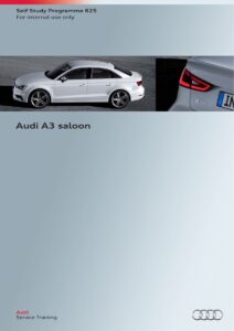
The sporty A3 saloon marks Audi's entry into the world's largest market segment, the compact four-door class. The third model in the successful A3 series features lightweight design, powerful and highly efficient engines, not to mention a number of high-end infotainment solutions and driver assistance systems. The Audi A3 saloon is the first notchback model from Audi in the compact premium segment and cuts an exceedingly sporty figure. The design of the Audi A3 saloon combines classic notchback styling with the dynamics of a convertible. The flat roof line terminates at the C post and merges seamlessly with the shoulder line. The tornado line is a prominent contour edge and the wheel arches are flared to give a muscular look. The large round air vents, the three-dimensional decorative inlays and the air conditioner’s elegant control panel are testimony to the attention to detail that Audi devotes to every vehicle.The large boot can be extended by folding down the rear seat backs. The sporty four-door model with its elegantly contoured notchback has all the strong-points of the successful A3 series.Production at the Györ plant The Audi A3 saloon and the S3 saloon are manufactured at the Győr plant in northwestern Hungary - the world's largest engine plant - where Audi has been assembling the TT Coupé, Roadster and A3 Cabriolet for a number of years now. The company has built in Györ a state-of-the-art automobile factory with a complete process chain. All stages in the production process – from pressing the sheet metal to final assembly – take place in an area covering 250,000 m2.625_0022
ContentsIntroductionIn brief ________________________________________________________________________________________________________________________________________________________ 4BodyIntroduction __________________________________________________________________________________________________________________________________________________ 6 Attachments __________________________________________________________________________________________________________________________________________________ 8 Joining technology ___________________________________________________________________________________________________________________________________________ 8 Effects of accident safety requirements on the body structure ________________________________________________________________________________________ 10 Vehicle architecture (MQB) _ ________________________________________________________________________________________________________________________________ 11 Underbody ___________________________________________________________________________________________________________________________________________________ 11Passive safetyComponents _________________________________________________________________________________________________________________________________________________ 12 System overview ____________________________________________________________________________________________________________________________________________ 13 In-car airbags ________________________________________________________________________________________________________________________________________________ 14 Sensors _______________________________________________________________________________________________________________________________________________________ 17 Front automatic belt retractor _____________________________________________________________________________________________________________________________ 21 Lap belt tensioner with buckle _ ____________________________________________________________________________________________________________________________ 22 Pedestrian protection _ ______________________________________________________________________________________________________________________________________ 26Active safetyAudi pre sense _______________________________________________________________________________________________________________________________________________ 30EnginesEngine/gearbox combinations _____________________________________________________________________________________________________________________________ 36 Petrol engines (China) ______________________________________________________________________________________________________________________________________ 38 Diesel engines _______________________________________________________________________________________________________________________________________________ 44 Exhaust system _ _____________________________________________________________________________________________________________________________________________ 47 Fuel system with SCR system ______________________________________________________________________________________________________________________________ 51SuspensionOverall concept ______________________________________________________________________________________________________________________________________________ 54 Suspension/steering versions _ _____________________________________________________________________________________________________________________________ 56 Low tyre pressure indicator ________________________________________________________________________________________________________________________________ 56 Wheels and tyres ____________________________________________________________________________________________________________________________________________ 57Electrical systemInstallation locations of control units ____________________________________________________________________________________________________________________ 58 Topology _____________________________________________________________________________________________________________________________________________________ 60Air conditioningAir conditioning system versions __________________________________________________________________________________________________________________________ 62InfotainmentOverview of versions ________________________________________________________________________________________________________________________________________ 64 LTE ____________________________________________________________________________________________________________________________________________________________ 66 Aerials overview _____________________________________________________________________________________________________________________________________________ 68 Sound systems ______________________________________________________________________________________________________________________________________________ 72 Map update service _________________________________________________________________________________________________________________________________________ 73 TV tuner ______________________________________________________________________________________________________________________________________________________ 74ServiceInspection and maintenance _ ______________________________________________________________________________________________________________________________ 76 Special tools and workshop equipment _ __________________________________________________________________________________________________________________ 78 Self Study Programmes ____________________________________________________________________________________________________________________________________ 79The Self Study Programme teaches a basic knowledge of the design and mode of operation of new models, new automotive components or new technologies. It is not a Repair Manual! Figures are given for explanatory purposes only and refer to the data valid at the time of preparation of the SSP. This content is not updated. For further information on maintenance and repair work, always refer to the current technical literature.NoteReference3
IntroductionIn briefThis Self Study Programme describes the modifications distinguishing the A3 ’13 from the A3 saloon. Several Self Study Programmes describing the design and mode of operation of the A3 saloon have been prepared for this purpose. You will find a list of the Self Study Programmes at the end of this Self Study Programme.Dimensions14169421555 1796625_0361555 1796625_037100639248692637 4456950625_0384688
13921145321423213451951 1000625_039Dimensions and weights Length in mm Width in mm Height in mm Track width, front in mm Track width, rear in mm Wheelbase in mm Trailer load in kg with brake at a gradient of 8 % Kerb weight in kg Max. gross weight in kg 4456 17966) 1416 1555 1526 2637 18004)Cabin width, front in mm Cabin width, rear in mm Headroom, front in mm Headroom, rear in mm Through-loading width in mm Load sill height in mm Boot capacity in l Capacity of fuel tank in l Drag coefficient in cw1453 1423 1006 924 1000 688 425/8805) 50 0.2913154) 1865Shoulder room width Elbow room width 3) Maximum headroom 4) with a 2.0l TDI engine developing 110 kW at 320 Nm 5) with the rear backrest folded down 6) excluding mirror1) 2)All dimensions are given in millimetres and refer to the unladen weight of the vehicle.5
BodyIntroductionThe body of the Audi A3 saloon documents the premium character of the A3 series. During the development of the car body, Audi's design engineers devoted special attention to reducing CO2 emissions. Thanks to Audi lightweight design technology, the A3 saloon has an unladen weight of only 1250 kg in the base version which comes with a 1.4 l TFSI engine and S-tronic. The Audi A3 saloon also conforms to the highest standards for vehicle safety. This is because it is manufactured entirely from materials that meet Audi's stringent quality standards.Ultra-high-strength hot-formed componentsHot-stamped steel makes up 24 % of the car body. These components are first heated in a furnace to over 1,000 °C and shaped immediately in a water-cooled pressing die, where they are cooled to about 200 °C within a very short time. This abrupt change in temperature creates an iron-carbon structure of exceptional tensile strength. Components made from these high-tech steels are relatively thin and therefore light.6
High-strength steel 30 %Ultra-high-strength steel (hot formed) 24 %Mild steel 28.5 % Modern high-strength steel 17 % Aluminium 0.5 %625_110625_109Ultrahigh strengthPartial temperingThe B post of the Audi A3 saloon is partially tempered in a shaping process. This imparts ultra-high-strength properties to the steel in the top and bottom sections of the B post and only high-strength properties to the steel in the mid-section. This way, the forces acting on the car body during a side impact can be effectively absorbed and the energy dissipated.High strength Ultrahigh strength625_1117
AttachmentsThe attachments, specifically the wings, doors, rear bumper crossmembers and rear hatch are of lightweight steel construction. The following components in the Audi A3 saloon are made of aluminium: • Front bumper cross-member • Bonnet • Rear window shelf A further reduction in car body weight was achieved by making selective use of aluminium.Joining technologyVarious joining technologies are used in the construction of the A3 saloon body. In addition to classic resistance spot welding (there are 4803 spot welds on the car), the following technologies are utilised: • • • • MAG welding (distance: 2520 mm) Laser welding (distance: 1,136 mm) Clinching (quantity: 14) Semi-tubular punch riveting (quantity: 65) Every car body features adhesive bonds with a total length of 60 metres. A high-precision connection between the side wall and the roof is achieved using a laser soldered seam. Upon completion, the seam is smoothed with brushes. This produces a virtually invisible seamless joint which highlights Audi's attention to detail. The seeams of the water outlets in the rear hatch area are made by plasmatron brazing. To save weight, the doors and window frames are pressed in one piece. The doors are welded in a state-of-the-art laser remote process.8
625_112Key: Ultrahigh strength steel (hot-formed) Advanced high strength steel High strength steel Low strength steel Sheet aluminium Aluminium section9
Ultra-high-strength hot-formed components Ultra-high-strength hot-formed components are installed in the following areas:1 2 3 4 5 6 Side member 2, left/right Upper footwell cross-member Lower footwell cross-member Inside left/right A post Inside left/right sill beam Tunnel7 8 9 10 11 Heel section reinforcement Cross-member Top left/right A post Rear left/right side member Inside left/right B post9 4 5 6 1 2 810 1173625_114Effects of accident safety requirements on the body structureModern car bodies are developed and designed on the basis of many different requirements. One of the key design criteria for vehicles is the safety of the occupants in an accident. The structure of the car body is a major factor determining whether and to what extent accident damage can be reduced or avoided. This behaviour is referred to as "passive safety". Country-specific regulations exist for different load cases, such as head-on collision and side impact. These country-specific accident safety requirements are met in the inside B post and inside lower beam/sill areas within both the ECE and NAR body versions of the A3 saloon.ECE versionNAR variant625_115 10625_116
Vehicle architecture (MQB)The body structure of the A3 saloon is based essentially on the body structure of the 3-door A3 '13. The underbody is based on the modules from the Modular Transverse Kit (MQB), which is subdivided into five basic vehicle sections. The key measurement is the distance between the foot controls and the centre of the wheel. The wheelbase of the A3 saloon has been extended by 35 mm (same as on A3 Sportback ’13) and the rear overhang by 165 mm.Wheelbase + 35 mmVariableUniformVariableRear overhang + 165 mmUnderbodyThe aim of the Modular Transverse Kit is to provide a flexible vehicle architecture. The number of variants and the complexity of components are significantly reduced by this modular strategy. The underbody of the A3 series consists of three modules – the front end, front floorpan and rear end.625_118The difference in underbody length required for the A3 saloon was achieved by extending the front floorpan and the rear end.625_119 11
Passive safetyComponentsDepending on country version and trim level, the passive occupant and pedestrian protection system in the Audi A3 saloon may comprise the following components and systems: • • • • • • • • • • Airbag control unit Driver airbag Passenger airbag Front and rear side airbags Head airbags Knee airbag, driver and passenger sides Front airbag crash sensors Crash sensors for side impact detection in the doors Crash sensors for side impact detection in the C posts Crash sensors for pedestrian protection in the front bumper cover • Crash sensors for pedestrian protection in the front foam moulding • Front inertia-reel seat belts with pyrotechnic belt tensioners • Front inertia-reel seat belts with electrical belt tensioners • Inertia-reel seat belts with active belt force limiters • Rear inertia-reel seat belts with pyrotechnic belt tensioners, driver and passenger sides • Lap belt tensioner, driver and passenger sides • Seat belt warning for all seats • Seat belt switches on all seats in the seat belt buckles • Seat occupancy sensor in front passenger seat • Front passenger airbag disabling switch • Passenger airbag OFF warning lamp • Driver and passenger seat position sensors • Pedestrian protection triggerAdditional equipmentEquipment specifications can vary due to the different requirements and statutory provisions for car makers in the various markets.Key to figure on page 13: E24 Driver side seat belt switch E25 Passenger side seat belt switch E224 Airbag disabling switch, passenger side E258 Rear seat belt switch, driver side E259 Rear seat belt switch, passenger side E609 Rear central seat belt switch G128 Passenger side seat occupancy sensor G179 Side airbag crash sensor, driver side G180 Side airbag crash sensor, passenger side G256 Side airbag crash sensor, rear driver side (C post) G257 Side airbag crash sensor, rear passenger side (C post) G283 Front airbag crash sensor, driver side (front end) G284 Front airbag crash sensor, passenger side (front end) G551 Belt force limiter, driver side G552 Belt force limiter, passenger side G553 Seat position sensor, driver side G554 Seat position sensor, passenger side G570 Driver side crash sensor for pedestrian protection G571 Passenger side crash sensor for pedestrian protection G598 Pedestrian protection trigger 1 G599 Pedestrian protection trigger 2 G851 Driver side crash sensor for pedestrian protection 2 G852 Passenger side crash sensor for pedestrian protection 2 J234 Airbag control unit J285 Control unit in dash panel insert J533 Data bus diagnostic interface (gateway) J706 J854 J855 K19 K75 K145 Seat occupancy recognition control unit Front left seat belt tensioner control unit Front right seat belt tensioner control unit Seat belt reminder warning lamp Airbag warning lamp Passenger airbag OFF warning lamp (PASSENGER AIRBAG OFF) N95 Driver side airbag igniter N131 Passenger side airbag igniter 1 N132 Passenger side airbag igniter 2 N153 Seat belt tensioner igniter 1, driver side N154 Seat belt tensioner igniter 1, passenger side N196 Rear seat belt tensioner igniter, driver side N197 Rear seat belt tensioner igniter, passenger side N199 Side airbag igniter, driver side N200 Side airbag igniter, passenger side N201 Rear side airbag igniter, driver side N202 Rear side airbag igniter, passenger side N251 Head airbag igniter, driver side N252 Head airbag igniter, passenger side N295 Knee airbag igniter, driver side N296 Knee airbag igniter, passenger side N297 Seat belt tensioner igniter 2, driver side (lap belt tensioner) N298 Seat belt tensioner igniter 2, passenger side (lap belt tensioner) T16 16-pin connector, diagnostic portNote The diagrams in the chapter entitled "Passive occupant safety" are schematic diagrams and serve to provide a better understanding.12
System overviewThe system overview shows the components for all markets. Keep in mind that this constellation is not possible in volume production.Key: Powertrain CAN bus Convenience CAN bus Diagnostics CAN bus Input signal Output signal625_05113
In-car airbags625_050Passenger airbagDue to the different statutory requirements of markets, two different versions of the passenger airbag are used in the Audi A3 saloon. Both airbags have canister-type gas generators. When compared to the passenger airbag modules in the Audi A3 '04 (which is equipped with tubular gas generators), the passenger airbag modules in the Audi A3 saloon have a weight advantage of around 25 %.Version 1 with passenger side airbag igniter 1 N131 A "single-stage" hybrid gas generator in used in this version. The passenger airbag in the Audi A3 saloon is identical to that in the Audi A3 ’13.Airbag connectorGas generatorHousing625_12314
Version 2 with passenger side airbag igniter 1 N131 and passenger side airbag igniter 2 N132 A "two-stage" hybrid gas generator in used in this version.Airbag connector socket (1st stage)Airbag connector (2. stage)Gas generatorHousing625_125New connector generation The ground cable, which connects the passenger airbag gas generator housing to the car body in both versions, has been integrated into the connecting plug of passenger side airbag igniter 1 N131. This ground cable is designed to protect the passenger airbag pyrotechnics against electrostatic discharge. After contacting the connector, the ground cable connects the gas generator housing to the body in an electrically conductive manner. The airbag connector is encoded mechanically.CoverLocking deviceContactMechanically encoded housing625_12415
Driver side knee airbagThe Audi A3 saloon is equipped with a knee airbag on the driver's side. The knee airbag is designed as a tubular-type cold gas generator. The driver side knee airbag is connected to the car body in an electrically conductive manner via the mounting brackets. To ensure that there is electrical conductivity, there must be sufficient contact between the mount and the body. The driver side knee airbag has a volume of about 14 litres. Please pay attention to the workshop manual.In-car mounting pointsKnee airbag igniter, driver side N295TabsKnee airbag625_122Passenger side knee airbagDue to the different statutory requirements of markets, the Audi A3 saloon also comes equipped with a knee airbag on the passenger side in some markets. This knee airbag has a tubular hybrid gas generator. The passenger side knee airbag is connected to the car body in an electrically conductive manner via mounting brackets. To ensure that there is electrical conductivity, there must be sufficient contact between the mount and the body. The passenger side knee airbag has a volume of about 20 litres. Please refer to the Workshop Manual.Knee airbag igniter, passenger side N296Knee airbag625_12616
SensorsFront airbag crash sensor, driver side G283 and front airbag crash sensor, front passenger side G284Due to the different statutory requirements of markets, two different versions of the front airbag crash sensors are used in the Audi A3 saloon. Front airbag crash sensors G283 and G284 are utilised in combination with the sensor integrated in the airbag control unit J234 for detecting head-on collision and rear impact. These are acceleration sensors which measure the car's longitudinal deceleration and acceleration during an accident.Version 1 In some countries, G283 is front-end mounted on the driver side and G284 is front-end mounted on the passenger side.Version 2 In other countries, only G283 is fitted. Although crash sensor G283 is designated "driver side", its installation location is "centre front end".625_052625_05317
Seat occupancy sensorDue to the different statutory requirements of markets, two different versions of the seat occupancy sensor with different functions are used in the Audi A3 saloon.Version 1 Passenger side seat occupancy sensor G128 The passenger side seat occupancy sensor G128 is an integral part of the seat belt reminder system. The airbag control unit J234 utilises the information supplied by the passenger side seat occupancy sensor G128 and the passenger side seat belt switch E25. If the passenger seat is occupied by person who is not weating a seat belt, the airbag control unit J234 detects this condition and issues audible and visual warnings. The sensor consists of two plastic films which are bonded together. On the inside of the films there are printed electrical conductor tracks and contact areas. The plastic films in the area of the contact sensors are kept apart using spacer film and are not bonded. Consequently, there is no contact between the contact films in the area of the contact sensors in the rest state. If weight is now placed on the seat occupany sensor, the films in proximity to the contact sensors are pressed together, reducing the total resistance to less than 120 ohms. At least one contact sensor on each side must be compressed before the passenger side seat occupancy sensor G128 determines that the seat is "occupied". If the passenger seat is unoccupied, the seat occupany sensor has a high resistance (approx. 470 ohms). The seat occupancy sensor is attached directly to the seat shell and no longer bonded to the seat cushion. The sensor is fitted with round and oblong-hole clips for exact positioning. The clips are prefitted on the sensor. In addition, the sensor is marked TOP and FRONT.625_056Passenger side seat occupancy sensor G128Connector plugContact sensorContact sensorBonded plastic filmsContact sensorContact sensorContact sensorContact sensor625_057Round clipOblong-hole clip18
Version 2 Passenger side seat occupancy sensor G128 with seat occupancy recognition control unit J706 The tank of this version of the seat occupancy sensor is to determine the occupancy status of the passenger seat. The following occupancy states can be recognised: 1. Seat not occupied or child seat fitted. 2. Seat occupied by an adult. The seat occupancy recognition control unit J706 evaluates the signals provided by the passenger side seat occupancy sensor G128. If the seat occupancy recognition control unit J706 detects a vacant front passenger seat, or a child seat on the front passenger seat, the passenger front airbag and the passenger knee airbag will be disabled by the airbag control unit J234. This means that the passenger front airbag and the passenger knee airbag would not ignite in the event of an accident which matches the criteria for deployment. If the seat occupancy recognition control unit J706 detects a front passenger seat occupied by an adult, the airbag control unit J234 will enable the passenger front airbag and the passenger knee airbag. In this case, the passenger front airbag and the passenger knee airbag would ignite in the event of an accident which matches the criteria for deployment. The occupants are kept informed by the passenger airbag OFF warning lamp K145 (PASSENGER AIRBAG OFF) as to whether the passenger front airbag and the passenger knee airbag are enabled or disabled. If the passenger front airbag and the passenger knee airbag are disabled, the passenger airbag OFF warning lamp K145 will be continuously lit. In addition, the airbag control unit J234 gives audible and visual warnings if the seat occupancy recognition control unit J706 indicates that the passenger seat is occupied by an adult and the passenger side seat belt switch E25 detects that this person is not wearing a seat belt.Passenger side seat occupancy sensor G128 The passenger side seat occupancy sensor G128 is a capacitive sensor and, put simply, acts as a capacitor. The capacitor comprises two plates (electrodes) and an insulator (dielectric), which is sandwiched between the two plates. When voltage is applied to one of the electrodes and the other electrode is connected to the battery's negative terminal, the capacitor begins to accumulate energy. Capacitance is measured in units called farads. The capacitance of a capacitor can be altered by changing the size of the electrode plate or the dielectric.DielectricElectrodeElectrode625_058Function In this version of the seat occupancy sensor, the passenger side seat occupancy sensor G128 and the car body represent the two plates of the capacitor. The size of these components is nonvariable. The dielectric consists of the seat cover, the atmosphere and the trim parts. It is, therefore, variable. When an adult is occupying the passenger seat, the dielectric between the passenger side seat occupancy sensor G128 and the car body changes due to this person's fluid content. The capacitance changes accordingly. If a child seat is placed on the passenger seat, the dielectric, and hence the capacitance, changes again. The change in capacitance is much smaller compared to an adult.Seat occupancy sensor, passenger side G128 Seat occupancy recognition control unit J706625_059 19
Installation location The passenger side seat occupancy sensor G128 is attached to the seat cushion. If the car is equipped with a seat heater, the passenger side seat occupancy sensor G128 is installed above the seat heater.Seat cushionPassenger side seat occupancy sensor G128625_060Seat occupancy recognition control unit J706In principle, the seat occupancy recognition control unit J706 is the measurement unit for the passenger side seat occupancy sensor G128. It detects the change in the capacitance of the seat occupancy sensor G128 and thus is able to determine the occupancy status of the passenger seat. The capacitance of the passenger side seat occupancy sensor G128 is measured cyclically by the seat occupancy recognition control unit J706. The airbag control unit J234 receives this information from the seat occupancy recognition control unit J706 via a LIN interface.Diagnostics The seat occupancy recognition control unit J706 is connected to the passenger side seat occupancy sensor G128 by a coaxial cable and supplied pre-assembled as a "service kit". The coaxial cable and the coaxial cable connector may not be repaired. Note that there are different seat types and therefore also different versions of seat occupancy recognition control unit J706. The software in the control units is adapted specially to the seat. If moisture has entered into the seat, e.g. due to a spilled glass of water, this can generate entries in the event memory of the seat occupancy recognition sensor. If the "service kit" is replaced, the basic setting procedure must be carried out. In this process, the serial number of the seat occupancy recognition control unit J706 is transferred to the airbag control unit J234.Contents of the service kitSeat occupancy recognition control unit J706Coaxial cable625_061Passenger side seat occupancy sensor G128Reference For further information about the passenger side seat occupancy recognition sensor, please refer to the Workshop Manual, the Guided Fault Finding and ETKA.20
Side airbag crash sensorThe side airbag crash sensors for the driver and passenger sides (G179 and G180) are capacitive pressure sensors. The pressure sensors have a new mounting concept and are no longer bolted. The pressure sensors are inserted into the sheet metal of the driver and passenger door and fastened by twisting. The seals seal off the system. The view shows the crash sensor locked in place, but without the door panel.FasteningPlug connectionSealTwisting tool625_146Reference For information on removing and installing the side airbag crash sensor, refer to the workshop manual.Front automatic belt retractorDepending on country of sale and equipment level, three different automatic belt retractors are used in the Audi A3 saloon. • Automatic belt retractor with belt tensioner • Automatic belt retractor with belt tensioner and reversible belt tensioner • Automatic belt retractor with belt tensioner, reversible belt tensioner and active belt force limiterAn Audi A3 saloon equipped with pre sense basic on the front automatic belt retractors has reversible belt tensioners with electric motors,y in addition to the pyrotechnic belt tensioners. The reversible seat belt tensioners together with the front left and right seat belt tensioner control units (J854 and J855 respectively) are connected to the airbag control unit J234 as LIN control units. When Audi pre sense basic detects specific driving situations, signals are sent to the data bus. The airbag control unit evaluates these signals and, if necessary, instructs the seat belt tensioner control unit to partially or fully tension the seat belts via an electric motor. For further information about Audi pre sense, refer to page 30. The automatic belt retractors use rack-type pyrotechnic belt tensioners. If an automatic belt retractor with seat belt tensioner control unit is replaced, the basic setting procedure must be performed using the "Guided Fault Finding" function.Seat belt tensioner control unitReversible belt tensioner with electric motorActive belt force limiterPyrotechnic seat belt tensioner625_086 21
Lap belt tensioner with buckleDepending on country of sale, the Audi A3 saloon comes equipped with seat belt tensioner igniter 2, driver side N297 and seat belt tensioner igniter 2, passenger side N298. The igniters are known as lap belt tensioners. If lap belt tensioners are fitted, the automatic belt retractors come fitted with a buckle. In the event of an accident, the lap belt tensioner works in conjunction with the buckle as follows: • Separation of the force acting on the pelvis from the force acting on the thorax • Reduced chest compression • Reduced upper thigh load • Reduced forward displacement of the pelvis • Improved interfacing between the pelvis and seatBuckleAutomatic belt retractorBelt end fitting Lap belt tensionerCoupling625_062Accident response sequenceIn the event of an accident which matches the criteria for deployment, the airbag control unit deploys the belt tensioners and the lap belt tensioners. The seat belt is tensioned from the buckle on up by the belt tensioner on the automatic belt retractor. For safety reasons, the belt force is limited by the active belt force limiter. The lap belt tensioner tensions the part of the seat belt between the occupant's pelvis and the buckle.625_063 22
Lap belt tensionerDesign The lap belt tensioner essentially consists of the following parts:Balls (guided by the piston and always in contact with the tube and locking cone due to the design of the piston)Piston with mounting for balls (movably attached to the steel cable)Steel cableCable seal (seals steel cable in pressure chamber)Tube with pressure chamberCoupling (connected to belt end fitting)Ring seal (seals off the pressure chamber) Pyrotechnic propellant chargeIgnition cable with connector625_069Locking cone (firmly connected to the steel cable)Function – ignition and lap belt tensioning When the airbag control unit J234 tensions the pyrotechnic propellant charge, the combustion of the propellant charge leads to a sudden rise in pressure inside the pressure chamber. The increase in pressure propels the piston including the balls, locking cone and steel cable towards the right. The cable seal and the ring seal seal off the pressure chamber externally.625_070Funktion – clamping Since the steel cable is connected to the seat belt coupling, the belt can be tensioned by up to 100 mm between the occupant's pelvis and the buckle. The steel cable and, with it, the locking cone are retracted slightly at the end of belt travel due to the forward displacement of the occupant. At the same time, high pressure is still present in the pressure chamber and at the piston. Due to the minimal backward movement of the locking cone and the counterforce acting on the piston (high pressure), the balls travel outwards along the sloping face of the locking cone and the tube deforms plastically. This prevents the seat belt from slipping back.Plastic deformation of the tubemax. 100mm625_071 23
Installation location of the lap belt tensionerThe lap belt tensioner is mounted to the sill by engaging the links on the lap belt tensioner in the sill and attaching the lap belt tensioner with two screws.Links engaged in the sill625_072Coupling The seat belt is deflected at the seat belt end fitting in the sill area and, unlike other vehicles, is movable longitudinally without the lap belt tensioner. A coupling is stitched to the end of the seat belt. The lap belt tensioner coupling is inserted into the seat belt coupling and clipped into place. To eliminate noise, a foam pad is fitted in the coupling area.Seat belt join Foam padBelt end fittingSteel cable of the lap belt tensioner Coupling625_064Diagnostics The lap belt tensioner is a pyrotechnic component. The safety instructions are the same as for other pyrotechnic components. The lap belt tensioner is damaged when ignited and has to be replaced as a unit. The airbag control unit J234 continuously monitors the lap belt tensioners for proper functioning.Faults in the system are registered by the airbag control unit as event memory entries. These faults can be cleared using the "Guided Fault Finding".BuckleThe difference between this seat belt buckle and a "regular" seat belt buckle is that it locks the belt in the event of an accident which matches the criteria for deployment. The result is a load path for the thorax region and a load path for the pelvic region, with all the aforementioned benefits for the occupants (refer to "Lap belt tensioner with buckle" page 22).625_06524
Design The buckle has a blocking element which is movably mounted in spring bearings. The blocking element is reversible during "normal" use. In the event of an accident, the lap belt tensioner tensions the seat belt in the pelvic region and the blocking element locks the belt by virtue of its geometry.CapSeat beltBlocking element with springBuckle625_066Function Unlocked LockedBlocking elementSeat beltBuckle625_067 625_068Reference For information on installing and removing the lap belt tensioner, please refer to the Workshop Manual and the Guided Fault Finding.25
Pedestrian protectionThe Audi A3 saloon is equipped with a system which can reduce the extent of head injuries sustainable by pedestrians in the event of a head-on collision. For this purpose, the bonnet is "displaced" to increase the distance between the bonnet and components in the engine bay and thereby create increase the "crumple zone".Crash sensors for pedestrian protectionTo enable the Audi A3 saloon to detect a collision with a pedestrian, it comes equipped with additional crash sensors: • • • • Driver side crash sensor for pedestrian protection G570 Passenger side crash sensor for pedestrian protection G571 Driver side crash sensor for pedestrian protection 2 G851 Passenger side crash sensor for pedestrian protection 2 G852G570 G571Acceleration sensors Crash sensors G570 and G571 are acceleration sensors. Acceleration sensors G570 and G571 are mounted on the back of the bumper cover, see Fig. 625_018.625_018Pressure sensors Crash sensors G851 and G852 are pressure sensors. Pressure sensors G851 and G852 come pre-mounted on a hose and form a unit. The hose is laid in a foam moulding and pressure sensors G581 and G852 are attached to an impact absorberG852 Impact absorberPressure hose Foam moulding (shock absorber)Mounting bracketClipG851 RivetCross member cover625_04826
Wiring A special feature of the wiring of the four crash sensors is that a pressure sensor and an acceleration sensor are connected to the same pins on the airbag control unit. For this purpose, the wires of two sensors are cross connected in the wiring loom. This is possible because the sensors send their signals in a timedelayed manner. This ensures that each signal is individually registered and processed by the control unit. The joins are about 95 ± 25 mm away from the connector of the airbag control unit J234.Airbag control unit J234Area of connection in wiring loomWiring loom95±25 mm625_055Function diagram625_024Key: G570 Driver side crash sensor for pedestrian protection G571 Passenger side crash sensor for pedestrian protection G851 Driver side crash sensor for pedestrian protection 2 G852 Passenger side crash sensor for pedestrian protection 2 J234 Airbag control unit27
Diagnosis of the crash sensors for pedestrian protectionDue to the wiring of the crash sensors for pedestrian protection, the event "open circuit or short to positive" can trigger different event memory entries depending on its location within in the wiring.Event before bundling of wires If an open circuit or short to positive is detected in a sensor wire before the wires have been bundled, the event "implausible signal" is registered for this sensor only.Event after bundling of wires If an open circuit or a short to positive is detected after the wires have been bundled, the event "open circuit or short to positive" is registered for both sensors.Open circuitOpen circuit625_096 625_095Pedestrian protection triggerThe pedestrian protection system triggers are pyrotechnic components comprising an igniter unit and cylinders with pistons. • Pedestrian protection trigger 1 G598 • Pedestrian protection trigger 2 G599 The same safety precautions apply as for airbags.625_029Igniter unitCylinder with pistonNote The system is non-reversible and must be repaired immediately. The car can still be driven to the nearest authorised repairer after the bonnet has been pushed back.28
FunctionIn the event contact with a pedestrian at a speed of between about 25 and 55 kph, the airbag control unit J234 activates both pedestrian protection triggers (G598 and G599). The propellant charges are ignited at the same time, and the developing gas pressure displaces the pistons in the pedestrian protection cylinders. The pistons are attached excentrically to the hooks, with result that the longitudinal motion of the piston causes the hooks to rotate. The hooks rotate away from the counter bearings and the pistons extend. Due to the kinematics of the bonnet hinges, the bonnet is displaced approximately 20 mm backwards and approximately 52 mm upwards at the back.Bonnet hinge in rest positionBonnet hinge deployedHinge attachment to bonnetHookPedestrian protection trigger G598, G599625_026Hinge attachment to wing stay625_027Event messageEvents in the system are indicated by the airbag warning lamp K75 in the instrument cluster (control unit in instrument cluster J285). In addition, the instrument cluster displays a warning triangle and the following text for six seconds after ignition "on". It reads: ”Safety system malfunction! See owner's manual“. The airbag control unit J234 continuously monitors the pedestrian protection system for proper functioning. Faults in the system are registered as event entries in the airbag control unit. For information about repair operations on the pedestrian protection triggers, refer to "External Body Repairs" in ELSA. The repair operations on the crash sensors for pedestrian protection are described in "Internal Body Repairs". A deployed system is indicated in the instrument cluster in much the same way as an event message.Opening the deployed bonnet The bonnet can only be opened in a deployed state if it has been displaced backwards. This is done as follows: on the left and right hand sides of the vehicle, push down on the bonnet with both hands at the hinge while simultaneously pushing forward (as shown) until the bonnet locks in its original position.625_028Reference For further information about the pedestrian protection system, please refer to the Owner's Manual, the Workshop Manual and the Guided Fault Finding.29
Active safetyAudi pre senseAudi pre sense is able to detect critical driving situations and initiate measures to prepare the car and its occupants for a potential impending collision. This is made possible by networking the various in-car systems. The systems send data continuously to the data bus. Other control units are able to evaluate this information and take appropriate action. Audi pre sense basic and/or Audi pre sense front are optional with the Audi A3 saloon. Please note that Audi pre sense cannot prevent collisions. It serves only to assist the driver and reduce the severity of the collision.Audi pre-sense basicLongitudinal dynamics function If the car is travelling forwards at a speed of over 30 kph (reverse gear is not selected) and the driver executes a "hazard braking manoeuvre" (whereby the brake pressure must reach a defined level), the reversible seat belt tensioners are partially tensioned under electrical power. If ESP (Electronic Stabilisation Program) is set to "Sport" or "Off" with the TCS/ESP button E256 or if Audi drive select is set to "dynamic", the seat belts are not partially tensioned.Drive profile selection switch module E592TCS/ESP button E256Handbookefficiency comfort625_087individual auto dynamicCar systemsSet individual625_088Emergency brake function During an "emergency braking" manoeuvre (brake pressure is at or exceeds a defined value for a defined period of time), the reversible seat belt tensioners are fully tensioned electrically. The airbag control unit J234 evaluates the signals which the ABS control unit transfers to the data bus. It instructs the seat belt tensioner control units, J854 and J855, to fully tension the seat belts, both electrically and reversibly. Depending on the situation, the ABS control unit J104 can instruct the hazard warning flashers to be activated.30
Transverse dynamics function If the Audi A3 saloon oversteers or understeers, the ESP system will attempt to stabilise the car. If the car becomes unstable because certain physical limits have been exceeded, the airbag control unit J234 initiates partial tensioning of the electrically reversible seat belt tensioners. If the car can no longer be stabilised, the electrically reversible seat belt tensioners are fully tensioned. At the same time, the side windows and the tilt/slide sunroof (if fitted) begin to close. • If ESP is set to "Sport" or "Off" or if Audi drive select is set to "dynamic", the seat belts are not partially tensioned. • If ESP is set to "Sport" mode or "Off", the seat belts are fully tensioned only if the driver actively applies the brakes.Crash function in the low speed range If the airbag control unit J234 detects a head-on collision with a low a rate of vehicle deceleration (no airbag deployment), it decides whether or not to fully tension the seat belts based on a situation-specific control unit algorithm. No further actions are initiated, e.g. activation of the hazard warning flashers, closing of the side windows or the tilt/slide sunroof (if fitted). System characteristics of Audi pre sense basic: • If a seat belt is not being worn or if the passenger airbag is set to "Off", the reversible seat belt tensioner is not activated. • The belt tensioner control units (J854 and J855 respectively) are connected to the airbag control unit as LIN control units. • The forward displacement of the front occupants can be reduced by more than 100 mm by tensioning the seat belts.Audi pre-sense frontThe optional Audi pre sense front system also comes with Audi adaptive cruise control (ACC). The ACC radar sensor which is integrated in the ACC control unit J428 monitors the traffic ahead of the vehicle and continuously measures the distance to a vehicle driving ahead. The ACC control unit evaluates the data and transfers relevant signals to the data bus. Other bus users receive the signals. The ACC control unit utilises these signals to initiates different actions via the control unit in the instrument cluster and the ESP control unit, if necessary.Front camera for driver assistance systemsAudi pre sense front is active even if the ACC system is not activated. Audi pre sense front has the following functions:ADriver information when following a vehicle ahead at a critical distance in certain situations.BIn the event of an impending collision with a moving or immobile vehicle, the system warns the driver and provides driver assistance via automatic braking or by increasing the brake force applied by the driver – thereby allowing a faster reaction time and reducing the car's speed. Full deceleration is provided in the event of an impending collision with a moving, stopped or stationary vehicle at a speed of less than 30 kph.625_054Radar sensorC31
Function AThe driver is warned visually if approaching another vehicle ahead and subsequently when following this vehicle at a critical distance and at a synchronised speed. The critical distance is defined as the distance at which a collision is likely to occur in the event that a vehicle ahead suddenly decelerates, even if the driver of the following vehicle reacts quickly.Approaching vehicle aheadSpeed SpeedFollowing at a critical distance including visual distance warning (ACC warning lamp)Collision625_089Function BWhen the car approaches a moving vehicle, the control unit in the instrument cluster J285 warns the driver visually and audibly when certain defined limits are exceeded. These warnings are issued within a certain period of time prior to the last braking opportunity for collision avoidance before the actual collision. The timing of warnings depends on the driver's degree of activity. Depending on steering, pedal and turn signal inputs, the system classifies the driver as active or inactive and, consequently, as attentive or inattentive. If the driver is classed as attentive, the warning will be issued later than a warning for a driver classed as inattentive. At the same time, the ABS control unit J104 prefills the brake system and modifies the deployment algorithms for Hydraulic Brake Assist. This means that Hydraulic Brake Assist begins to build up brake pressure even at low brake pedal actuation speeds. If the driver does not respond to the warnings or, for example, eases off the accelerator, the ABS control unit J104 produces a warning jolt. The warning jolt is a very brief, but easily noticeable, braking impulse and does not slow the car down. It alerts the driver to the traffic situation and indicates to the driver that he must react immediately in order to prevent an impending collision. Depending on how attentive the driver is considered to be, the warning jolt will be produced within a certain time window ahead of the last opportunity to brake or take evasive action to avoid a collision. If the driver still fails to react or only eases his foot off the accelerator, the system will initiate partial braking operation I, which involves applying up to 35 % of maximum brake force. If the car is fitted with a front camera for driver assistance systems R242 and this camera also detects the obstacle, brake force is increased to up to 60 % via partial braking operation II. If the driver applies braking, a target braking maneouvre may be performed in all of the phases described above (prefilling of the brake system, reconfiguration of Hydraulic Brake Assist, driver warning, warning jolt, partial braking operations I and II). During the target braking manoeuvre, Audi pre sense front computes whether the driver is applying sufficient brake force to be able to avoid a collision. If this is not the case, the required brake pressure is increased depending on the situation.Prefilling of the brake system Hydraulic Brake Assist reacts with heightened sensitivityVisual/acoustic driver warning (forward collision warning)Warning joltPartial braking operation I or partial braking operation II (on models with front camera for driver assistance systems)CollisionTarget braking625_090 32
Function CAudi pre sense front also includes a function for "full deceleration at speeds from 0 to 30 kph". If the ACC control unit detects an impending head-on collision when the car is travelling at a speed of less than 30 kph, the ABS control unit J104 prefills the brake system. The deployment algorithms for Hydraulic Brake Assist are adjusted at the same time. Hydraulic Brake Assist thus starts building up brake pressure, even at low brake pedal actuation speeds. If the driver fails to brake or does not apply sufficient braking force in a critical situation, the ABS control unit J104 executes a braking maneouvre and applies near-maximum braking if necessary. Shortly before the system deploys, the driver is alerted by audible and visual warnings that the car is about to brake automatically or provide braking assistance. If the Audi A3 saloon has automatically brought the car to a halt without driver intervention, three more audible signals will sound. These signals alert the driver to the fact that he must actively take control of the vehicle (e.g. by applying braking). If the driver fails to take control of the vehicle, e.g. in a model with automatic transmission, the system will release the brake and the vehicle will start to move.Prefilling of the brake system Hydraulic Brake Assists reacts with higher sensitivityFull deceleration with visual and audible driving warning prior to interventionCollision625_091System characteristics with regard to "full deceleration at speeds of less than 30 kph" • The driver is not prewarned. • The system does not react to crossing or oncoming vehicles and objects with a low radar signature (e.g. pedestrians). • The system reacts to vehicles which are travelling in the same direction, have stopped or are immobile.Driver prioritisation over system If the driver takes clear evasive action, accelerates or brakes during the individual phases of Audi pre sense front (functions A to C), the momentary actions of Audi pre sense front (e.g. partial braking operation I) will be suppressed or cancelled. If the obstacle is no longer relevant after the evasive action has been taken, any assistance provided by Audi pre sense front will be cancelled in this case.33
Settings and displaysDeactivating Audi pre sense There are two options for deactivating Audi pre sense in the MMI. • Version 1: Prewarning off – the audible and visual warnings (distance and forward collision warnings) are off. • Version 2: System off – the audible and visual warnings (distance and forward collision warnings), warning jolt, partial and target brakings and "full deceleration at speeds below 30 kph" are deactivated. CAR - Systems System Early warning Audi pre sense HandbookBoth versions of Audi pre sense are activated.625_092Activating Audi pre sense From calendar week 45/2013, the previous procedure for reactivating Audi pre sense in all A3 derivatives will change as follows: A deactivated "system" function reactivates itself automatically if the ignition is turned off and on again. If only the "prewarning" function has been deactivated, this function must be activated via the MMI up until calendar week 22/2014. From calendar week 22/2014, a deactivated "prewarning" function will reactivate itself automatically the next time the ignition is turned on after a terminal 15 cycle (ignition off/on). A deactivated "system" function or a deactivated "prewarning" function can of course be activated in the MMI at any time. Self Study Programme 609 "Audi A3 ´13" describes how vehicles built prior to calendar week 45/2013 behave.Influence of ESP on Audi pre sense If ESP (Electronic Stabilisation Program) is set to "Sport" or "Off" using the TCS/ESP button E256, then the audible and visual warnings, the warning jolt, the partial and target brakings, and "full deceleration at speeds below 30 kph" of Audi pre sense will also be deactivated. Audi pre sense remains deactivated until: • ESP is reactivated with the TCS/ESP button E256. • The ignition is turned off and on again, thereby reactivating ESP. • ACC is activated, since this would result in automatic activation of ESP. If ESP (Electronic Stabilisation Program) is set to "Sport" or "Off" using the TCS/ESP button E256, the following text is temporarily displayed on the control unit in the instrument cluster J285: "Audi pre sense: off".Reference For further information about ACC, refer to Self Study Programme 612 "Audi A3 ’13 Suspension". For further information about the front camera for driver assistance systems R242, refer to Self Study Programme 611 "Audi A3 ´13 Vehicle Electronics and Driver Assistance Systems".34
Data bus overviewThe overview shows, by way of example, some of the information exchanged via data bus.ABS control unit J104 Prefill brake system ← E Warning jolt ← E Partial braking operations I and II ← E Target braking ← E Driving speed → A Wheel speed FR → A Wheel speed FL → A Wheel speed RR → A Wheel speed RL → A Brake pressure → A TCS / ESP status → A Activate hazard warning flashers → A Longitudinal acceleration → A Transverse acceleration → A Rotation about vertical axis → A Cruise control unit for adaptive cruise control J428 Prefill brake system → A Warning jolt → A Partial braking operations I and II → A Target braking → A Audible and visual warnings → A Display "Audi pre sense" system malfunction → A Steering angle ← E TCS / ESP status ← E Accelerator position ← E Brake pressure ← E Wheel speed FR ← E Wheel speed FL ← E Wheel speed RR ← E Wheel speed RL ← EOnboard power supply control unit J519 Reversing light switch status → A Close sliding sunroof ← E Close sliding sunroof → A (to LIN user sliding sunroof control unit J245)Sliding sunroof control unit J245 Close sliding sunroof ← E (LIN user of onboard power supply control unit J519)Instrument panel control unit J285 Audible and visual warnings ← E Display "Audi pre sense" system malfunction ← EPower steering control unit J500 Steering angle → ASteering column electronics control unit J527 Information electronics control unit 1, J794 Audi drive select set-up → A Cruise control system status → AAirbag control unit J234 Seat belt buckle status → A Passenger airbag status → A Close side windows → A Close tilt/slide sunroof → A Electrical partial tensioning → A (to LIN users front left and right seat belt tensioner control units, J854 and J855 respectively) Electrical full tensioning → A (to LIN users front right and left seat belt tensioner control units, J855 and J854 respectively) Seat belt tensioning status → A Wheel speed FR ← E Wheel speed FL ← E Wheel speed RR ← E Wheel speed RL ← E Longitudinal acceleration ← E Transverse acceleration ← E Rotation about vertical axis ← E Vehicle speed ← E Brake pressure ← E TCS / ESP status ← E Accelerator position ← E Audi drive select set-up ← E Reversing light switch setting ← E Steering angle ← EEngine management control unit J623 Accelerator position → ADoor control units J386, J387, J388, J389 Close side windows ← EFront left belt tensioner control units J854 (LIN user of airbag control unit J234) Electrical partial tensioning ← E Electrical full tensioning ← EFront right belt tensioner control units J855 (LIN user of airbag control unit J234) Electrical partial tensioning ← E Electrical full tensioning ← EKey:Data bus in general LIN bus← E Receiving data (input) → A Sending data (output)625_09435
EnginesEngine/gearbox combinationsThe engine-gearbox combinations shown below are those available at market launch. The specific features of Chinese-spec petrol engines and US-spec diesel engines will be explained on the following pages.Petrol engines1.4l TFSI engine0AJ0A4/02S0CW1.8l TFSI engine02S0CW0D9 front2.0l TFSI engine0D9 quattro 0CQ0FB0D9 quattro0CQ36
Diesel engines1.6l TDI engine02S0CW2.0l TDI engine02Q front02Q quattro0D9 front0CQGearbox codes:0AJ 0A4 02S 02Q 0FB 0CW 0D9 0CQ (MQ200_6F) (MQ250_5F) (MQ250_6F) (MQ350_6F/6A) (MQ350_6A) (DQ200_7F) (DQ250_6F/6A) Rear axle final drive unit (5th generation Haldex coupling)Breakdown of manufacturer codes: e.g. MQ350-6FM D Q 350 6 F A Manual gearbox Twin-clutch gearbox Transverse installation Nominal torque capacity Number of gears Front wheel drive All-wheel drive (quattro)Reference For a technical description of the engines and gearboxes, refer to the relevant Self Study Programmes (see overview on page 79).37
Petrol engines (China)These engine modifications were made because China presently has no national exhaust emissions standard equivalent to EU6.1.4l TFSI engine CSSA Technical featuresExhaust turbocharger with wastegate flap (pneumatically actuated)625_098Engine management system625_100• Engine control unit with adapted hardware for MED 17.5.25, made in China. • Software modifications: • Modified exhaust gas backpressure • Activation of the high-pressure fuel pump • Activation of the pneumatically actuated wastegate flap on the exhaust turbocharger38
Bosch high-pressure fuel pump625_099• • • • • Operating pressure: 30 to 200 bar Drive via 4 lobe cam Pressure limiting valve is integrated in the high-pressure pump Compatible with ethanol fuels up to E100 Pressure pulsation damper integrated in the high-pressure fuel pump • When de-energised, fuel pressure regulating valve N276 is open, i.e. no high fuel pressure is built upSpecial features of the crankshaft drive system and valve gear • Pistons are cast with a ring land • Optimised intake valve springs • Polymer-coated small-end conrod bearings These modifications are necessary because irregular pressure conditions can occur during the combustion process due to differences in fuel quality.Special features of the exhaust system • Starter and main catalytic converters • Twin oxygen sensors (bistable sensors)625_101Miscellaneous • First oil fill: VWTL52167 (SAE 5W-40)39
CUFA 1.8l TFSI engine Technical featuresCylinder head without integrated exhaust manifold625_105Cast steel exhaust turbocharger with wastegate flap (pneumatically actuated)40
Intake manifold module without MPI injectors625_106Coolant regulator with thermostat (expanding material element)625_104625_107 41
SpecificationsTorque/power curves 1.4l TFSI engine with engine code CSSA (China) Power in kW Torque in NmEngine speed [rpm]625_101 625_102Engine code Type Displacement in cm3 Power output in kW (hp) at rpm Torque in Nm at rpm Number of valves per cylinder Firing order Bore in mm Stroke in mm Compression ratio Engine management system Fuel Emission standardCSSA Four-cylinder in-line engine 1395 110 (150) at 6000 250 at 1500 — 3500 4 1–3–4–2 74.5 80 10.5 : 1 Bosch MED 17.05.25 Premium unleaded 95 RON EU 5 CN42
1.8l TFSI engine with engine code CUFA (China) Power in kW Torque in NmEngine speed [rpm]625_104 625_117Engine code Type Displacement in cm3 Power output in kW (hp) at rpm Torque in Nm at rpm Number of valves per cylinder Firing order Bore in mm Stroke in mm Compression ratio Engine management system Fuel Emission standardCUFA Four-cylinder in-line engine 1798 132 (180) at 4200 – 6200 300 at 1450 — 4200 4 1–3–4–2 82.5 84.1 9.6 : 1 Simos 18.3 Premium unleaded 95 RON EU 5 CN43
Diesel engines2.0l TDI engine Technical featuresCylinder block with integrated balancer shafts625_030Oxidising catalytic converter and diesel particulate filter625_019Cylinder head with variable valve timing (engines compliant with EU 6 exhaust emissions standard)625_03144
Oil pump with integral vacuum pump625_032Switched coolant pump625_033Intake manifold module with integrated intercooler625_035625_03445
Specifications of 2.0l TDI engineTorque-power curve Engine with engine code CRUA (USA) Power output in kW Torque in Nm625_082Engine speed [rpm]625_023Engine code Type Displacement in cm Stroke in mm Bore in mm Cylinder spacing in mm Number of valves per cylinder Firing order Compression ratio Power output in kW at rpm Torque in Nm at rpm Fuel Engine management system Maximum injection pressure in bar Emission standard CO2 emission in g/km3CRUA Four-cylinder in-line engine 1968 95.5 81.0 88.0 4 1–3–4–2 16.2 : 1 110 at 3500 - 4000 320 at 1750 - 3000 Diesel to EN 590 Bosch EDC 17 2000 with solenoid injector CRI2-20 BIN 5 – Tier 2 106Reference For further information about the design and mode of operation of the 2.0l TDI engine, refer to Self Study Programme 608 "Audi 1.6l / 2.0l 4-cylinder TDI engine".46
Exhaust systemExhaust gas treatment moduleTo achieve the EU 6 emission limits with the Modular Transverse Kit (MQB), an NOx aftertreatment system is used in lightweight vehicles (dependent on flywheel mass class). The BIN 5 Tier 2 emission limits necessitate using an SCR system. Versions Depending on model version and exhaust gas treatment module, a distinction will be made in future between: • System with NOx accumulator catalyst (NSK) in Europe • System with Selective Catalytic Reduction (SCR) in the USAInstallation listDepending on the exhaust emission standard which the engine is designed to meet, various additional components are used on the engine and on the exhaust system. Features High pressure exhaust recirculation Low pressure exhaust recirculation Cooled exhaust recirculation valve Uncooled exhaust recirculation valve SCR system (AdBlue) EGR cooler Additional temperature sensor at radiator outlet Oxidising catalytic converter with SCR-coated diesel particulate filter NOx accumulator catalyst and diesel particulate filter with integrated oxidising catalytic converter and hydrogen sulphide barrier coating Cylinder pressure sensor x 1 1 4 x x x x x x The following table provides a summary of the various components used.EU 4 xEU 5EU 6 xEU 6 (heavy duty) x x x x x xBIN5 x x x x x x x xxx x xExhaust system for EU 6 engines without SCR systemIt consists of the NOx accumulator catalyst, the diesel particulate filter with integrated oxidising catalytic converter and a hydrogen sulphide barrier coating. NOx and sulphur load are computed on the basis of various characteristics and stored as a model in the engine control unit. Two oxygen sensors monitor and regulate the combustion process.TurbochargerNOx accumulator catalystDiesel particulate filter with oxidising catalyst and hydrogen sulphide (H2S)barrier coatingEGR coolerExhaust gas treatment moduleExhaust flap control unit J883625_040 47
Exhaust gas treatment module without SCR system The exhaust gas treatment module has two oxygen sensors. The oxygen sensor upstream of the NOx accumulator catalyst, oxygen sensor G39, is responsible for regulating the air-reduced operating modes. It also serves as the input variable for the model which is used in the engine control unit to determine the engine's NOx and soot emissions. A surplus of reducing agent during the regeneration phase is detected with the aid of the second oxygen sensor - oxygen sensor after catalytic converter G130 - and used