

TECHNICAL DOCUMENTATION
SSP 200 Golf IV
Loading PDF…
Read document text
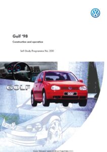
Syntax Error: Couldn't read xref tableSyntax Warning: PDF file is damaged - attempting to reconstruct xref table...Syntax Error: Missing 'endstream'Golf ‘98Construction and operationSelf-Study Programme No. 2001 Dieses Dokument wurde erstellt mit FrameMaker 4.0.2.
Dear Reader,The Self-Study Programme series has been keeping you informed about the construction and operation of Volkswagen and Audi technology for the past 24 years .• The contents are based on the workshop manuals. • The chapter entitled “Servicing” informs you about changes in our servicing procedures. We hope that the Self-Study Programme will provide you with useful information and assistance in your daily work.In conjunction with the launch of the new Golf, we have taken the opportunity to revise slightly the layout of our Self-Study Programme.• In keeping with the times, the style of our Self-Study Programmes is now friendlier and more easily distinguishable. With kind regards of your Self-Study Programme Team K-VK-12ONE for ALL?ALL for ONE!You can find your new Golf in the middle of the Self-Study Programme.NewImportant NoteThis Self-Study Programme is Please refer to the relevant Service literature for all inspection, not a Workshop Manual. adjustment and repair instructions.2
At a glanceAn all-new Golf............................................................ 4News Vehicle dimensions Environmental protection, recycling Occupant protection, anti-theft measuresBody .............................................................................. 18Fully galvanised body High-strength panels BumpersEngines .......................................................................... 23Engine-gearbox combination Engine Cruise controlPower transmission ..................................................... 38Manual gearbox Automatic gearboxRunning gear ................................................................ 40Steering Front axle/rear axle Braking system Wheels/tyresElectrical system .......................................................... 49Vehicle electrical system Convenience system Headlights Rain sensorHeating, air-conditioning system .............................. 57Heating Manual air-conditioning system ClimatronicService ........................................................................... 60Body New special tools3
An all-new GolfS W E N S• W E •N S W NE • S 974 h 2, 1 c r a NEW nMEW N • S W E N S• W E •N S d W Golfe • NE1974, e c n i S F... L O the Gdective n i t s i d ep ith its ed a r . . . w s establish a sign h as a highly . n o i t ehicle uta atic v m s i r a chourth The f tion ra geneGOLFO or ccess the su eetle B to the led off l o r t line. firs uction d o r p thed The legen d n o n sec wage s k l o of V lue nd-b instr ts umen... y t e f Sahting ent lig m u r t s e In ions d-blu e vers y red-an ble in thre c capabilit a i l t i s a o v -a iagn self-d - hasa Red-e pronts ar sysa p u c n c The o y a moder b t d l e e t tec ng b t force l eaturi tem f ers and be n o i s n te o rs, tw limiteNew hts lig headn. evel trim l evel versio h g i l H y entr in thede and si s g a b r t seat ize ai full-s in the fron s airbag ts. es backrBodytheir show kd n a r e inctiv x inner wo e l p m co ings....with Seat y or memar 12-ye ty n warraved s deri t h g i l ad val he round The o e original ly disth th from hts are hig g i l head4 4
S W E N WS •The n ew m odel like a looks d again an Golf andew st n sets ards.S• W E •N S W NE • S • NEWment velop e d y r n. tiona evolu Golf desig andard e h t s s i st s It lassle h technical the c e h t to ig of cts a h re superior e l f e r o It theref and is ition. et comp new of the at the % 0 9 Over recyclable ul s ef f l Go i its long us g f o v r d e s in en s con ces for u h t , e lif sour ble re f generaa u l a v o nefit the be come. to tionsafety ...Ss olf ha new G ide ime h t f o ts cture gains ty stru ptimised a ll area. e f a s The otwe lly o ver fo specia been d in the dri n pact ake of a s e For th ironment: nv the eenConv syse c n ie temSafeience onven decenc e h T has a system layout. d traliseWOB - VK 12olf f the G and o y d o erseal ised b alvan f PVC und ehicle by g y l l u o The f bout 4 kg ife of the v a ll s u e f e v sa e us h t s d exten 30%.HELP GNO NDIA - EIGE tronik V.A.G relek 01 - Moto SE3 1 2 6 4 5 9 7 8 Q C 0HELPPRINT5
An all-new GolfS• W E •N S W roven NE • e the p al r a S f l Go nu EW in the tic and ma N • a m to S W es. xes aue E o b r arbox N a g • e g The EWS N • S W E N • are sngin The e esrful. powe sed d n a ni rn mode n a harmo pt, o d n e co ce Bas icient f f e l fue mi low e leve v e i ch igh they a d offer a h rt. an fo sions iving com r d f el oS NEWA eerin ge nti-thasu ft meress asure of me pror e b o A num en taken t theft e b ve i t e c v ha effe e r o vide m ion. t protect The sng as steeri ent of r e w o m The p the adjust ering s te a s l l t f e w d-a n a e r dded the fo provide a n colum t. r comfo earAunni The rng gunf the r o n o i t ents nterac The i ar compon f drive lo ning g good leve a s e giv . mfort ing coter, n hea g e e w t ionin se be Choo air-condit tronic. l A a manu and CLIM systemditio ir conningThe Golf isagen w s k l Voront The faxleear The raxle6 6
Vehicle dimensionsthe “+ dimensions“ in the drawing are comparative values with the predecessor modelWidth Height Track width, front1735 mm 1439 mm+ 40 mmAerodynamic drag=Drag coefficientxFrontal area, projected surface area+ 35 mmcd 0.65 m2 = 0.31x xA m2 2.1 m2 Length Wheelbase 4149 mm 2511 mm+ 39 mm + 131 mmRear track width Through-loading width1494 mm 1005 mm1005 mmTank capacity55 litres+ 34 mmSSP 200/066+ 16 mm1513 mm7
An all-new GolfEnvironmental protectionThe Volkswagen Group is making eco-efficient, progressive technologies available world-wide. It employs these technologies throughout the life cycle of its products and beyond.Recycling at a high level In stripping centres the parts removed from scrap cars are sorted into clean material streams according to type and then recycled. In many cases, plastics, metals and insulating materials can even be made into the original product again.The overview below shows what materials are used in the Golf:34 kg 44 kg 12 kg 174 kg 10 kg 27 kg 14 kg 17 kg 58 kgSSP 200/008Glass Rubber Insulating materials Plastics Paint Light alloys Electrics/cable Non-ferrous metals Petroleum/oil/grease Miscellaneous Steel/iron Total weight3.1% 4.0% 1.1% 16.0% 0.9% 2.5% 1.3% 1.6% 5.3% 0.2% 64.0%2 kg 696 kg 1088 kgOn the following pages we will explain to you our eco-friendly policy on raw materials using insulating materials as an example.8
RecyclingPrinciple: • Avoidance comes before reduction • Reduction comes before recovery • Recovery comes before disposalRenewable raw materials are used every vehicle. Their recyclability is a major factor. The raw materials which are made into components are processed and recycled.Recycled insulating materialsCotton fibre fleece in insulating mats and luggage compartment floor coveringsFor example, the c o t t o n f i b r e f l e e c e used in insulating mats is a recyclate of garment cuttings. Waste fibre recovery is industry’s contribution to reducing the burden on waste disposal sites.Trims and covers made from renewable materials0.5 kg flax fibre moulding material used for the tailgate trim0.8 kg flax fibre moulding material for seat backrest cover 2.1 kg flax fibre moulding material used for the wheelhouse trimF l a x f i b r e m o u l d i n g m a t e r i a l is contained in trim panels and covers. The straw left over from the linseed harvest was burnt for many years. However, approximately 25% of fibre component can be used as a basic material for fibre mouldings. The quality of the fibres need not meet the high standards of the textile industry, but it does satisfy the high quality standards for trim panels. Flax fibres are highly workable and have excellent material properties.1.5 kg wood fibre moulding material in the doors and side panelsSSP 200/009W o o d fSyntax Error: Missing 'endstream'Syntax Error: Page tree object is wrong type (stream) i b r e m o u l d i n g m a t e r i a l is used for trim panels. The basis of wood fibre moulding materials are the pine woodchips left over from the production of wooden beams and boards in sawmills. Wood fibre moulding material meets the requirements of the automobile industry. These include: low weight, low emissions, high strength and non-splintering properties.9 9
An all-new GolfOccupant protectionThere is more to occupant protection than the airbag, belt tensioner and stable side protection. Most of the impact energy is absorbed by the car body. Achieving such a high standard of safety means paying special attention to detail.The front seat belts have two pyrotechnical belt tensioners which operate according to the same principle as the rotary-piston engine.The full-size airbags for the driver and front passenger sides are almost twice the size they were before. 64 litres 120 litresSSP 200/013You can read about the design and function of this seat belt tensioner in Self-Study Programme No. 192.SSP 200/011A 3-point seat belt and a 3rd head restraint The side airbags for the driver and front passenger. are available for the rear middle seat. The rear seat belts do not have belt tensioners.12 litresSSP 200/1210SSP 200/014
Lashing eyes The four lashing eyes in the luggage compartment enable luggage to be secured safely.The paddings are integrated in the door and side trims. They protect the pelvis and rib areas of occupants during a side impact.SSP 200/016The child safety seat fastening systemSSP 200/015Welded on the vehicle body are retaining eyelets to which child safety seats equipped with the ISOFIX fastening system can be easily secured.The fuel tank is now located in front of the rear axle for added safety in a rear collision.SSP 200/018 SSP 200/01711
An all-new GolfAnti-theft measuresA number of measures have been taken to provide more effective theft protection.Lock cylinder freewheel in tailgate lock - Inner-profile key - Lock cylinder freewheel for steering wheel lock - Slip clutch on steering columnAnti-theft alarmBonnet lock cover- Lock cylinder freewheel in outer door handle - Encapsulated internal door lock with central locking and SAFE featureSSP 200/076ImmobiliserThe door lock is encapsulated and there is a metal reinforcement around the door lock. These measures prevent would-be thieves piercing a hole through the bodyshell in this area and levering open the door handle.The bonnet lock cover makes breaking open the bonnet more difficult.SSP 200/077SSP 200/07812
Anti-theft measuresThe steering system The striker pin of the ignition lock can no longer be sheared off. This makes it impossible to steer the vehicle.Steering columnBushA corrugated tube is located on the steering column. A bush with oblong holes is press-fitted on it. The steering column and the bush joined by an interference fit via the corrugated tube.Corrugated tubeStriker pinThis is how it works: The striker pin of the ignition lock engages in the oblong holes of the bush when the ignition key is removed from the ignition. If an attempt is made to turn the steering wheel by applying a force of approx. 150 Nm, the corrugated tube will be friction-locked between the steering column and bush. It is not possible to steer the vehicle or shear off the locking pin.SSP 200/073BushSteering column Corrugated tubeStriker pinInserting the ignition key in the ignition withdraws the striker pin from the oblong holes of the bush. The vehicle can again be steered since the corrugated tube and the bush now rotate with the steering column.Striker pinSSP 200/07413
An all-new GolfAnti-theft measuresThe lock cylinder freewheel is integrated in the front doors, tailgate and ignition lock. It prevents these locks being forced and limits the damage caused by an attempted break-in.The lock-cylinder unit comprises the following components:Lock cylinder Locking plate Clutch Door operating linkageLock cylinder housingFreewheel sleeveSliding ringFunction of door lock cylinder freewheel shown below using a door lock as an exampleSSP200/108When the key is not inserted in the ignition, the locking plates engage in the freewheel sleeve.Lock cylinderLocking plate Freewheel sleeveSSP 200/13114
Door lock Door operating linkageSliding ring Lock cylinder Freewheel sleeveInserting the matching key in the ignition draws the locking plates into the lock cylinder. When the ignition key is turned, the lock cylinder in the freewheel sleeve rotates and opens the door lock via the sliding ring and the door operating linkage.KeySSP 200/132Door lock Door operating linkageSliding ringLocking plate Freewheel sleeve Cam inside lock cylinder housingIf the wrong ignition key is used or another tool, the locking plates remain in the freewheel sleeve. When the lock cylinder is turned, the freewheel sleeve is also rotated. The freewheel sleeve and the sliding ring are moved by two cams inside the lock cylinder housing. In the process, the lock cylinder is disconnected from the sliding ring. The lock cylinder turns without the sliding ring or the door operating linkage. The door lock is not opened.SSP 200/133The lock cylinder freewheel and the encapsulated internal door lock minimise damage caused by an attempted break-in.15
An all-new GolfAnti-theft measuresImmobiliser This is an electronic theft deterrent. It is activated when the ignition is turned on. The immobiliser prevents unauthorised persons from operating the car by intervening in the engine control unit. The differences between the 2nd generation immobiliser and the previous generation are as follows: • The immobiliser control unit is integrated in the dash panel insert. • In addition to the fixed code, the engine immobiliser control unit transmits a self-varying code to the transponder integrated in the vehicle ignition key.Reader coil on ignition lockEngine immobiliser control unit integrated in dash panel insert Ignition key with transponder Engine control unitSSP 200/064After the ignition is turned on, the transponder sends a fixed code to the engine immobiliser control unit. If this code is correct, a self-varying code is generated in the engine immobiliser control unit by a random generator. The selfvarying code is transmitted to the transponder inside the vehicle ignition key. This starts a series of secret arithmetic operations in the transponder and the engine immobiliser control unit.If these arithmetic operations produce identical results, the vehicle key is recognised as the correct one. As before, a check is performed to see if the self-varying code of the engine immobiliser control unit and the engine control unit match. If they match, the vehicle is ready to operate. The advantage of these secret arithmetic operations is that the calculated self-varying code cannot be decoded. In addition, the vehicle ignition keys cannot be copied.16
Anti-theft measuresAnti-theft alarm This monitors the doors, the bonnet, the tailgate and the ignition lock. The function can be integrated in two different control units:In the central locking control uniton vehicles without electric windowsIn the central control unit for the convenience systemon vehicles with electric windowsMicroswitch in door locks Microswitch in tailgate lock Microswitch in door locksMicroswitch in bonnet lockIndicator lamp for central locking/SAFE locking system Ignition lockWOB -Central control unit for convenience system or central locking control unitVK 1 2Indicator lightsSSP 200/112Signal horn for anti-theft alarmThe anti-theft alarm is switched on when the vehicle is locked once with the ignition key. To lock the vehicle without switching the antitheft alarm on, the vehicle must be locked twice within a period of 5 seconds.If the vehicle is broken into in one of the monitored areas, a signal is sent to the control unit and the alarm is tripped. The alarm is reproduced audibly by activating the signal horn for the antitheft alarm and visually by activating all the indicator lights. Syntax Error: Weird page contentsSyntax Error: Invalid page count in page treeDepending on the car’s specification, the selfdiagnosis can be performed using - address word 35 in the central locking control unit or - address word 46 in the convenience system central module.17
Front bumperIn a frontal collision at speeds of up to approx. 15 kph, the bumper together with the cross member absorb enough energy to prevent the side members from being damaged.Side member Cross memberBumpersSSP 200/023Rear bumperThe rear bumper has been enlarged. As a result, a low-speed rear collision does not cause damage to the body side section.These measures will reduce repair costs.SSP 200/12321
Technical platformLike the Audi A3 and the Skoda Octavia, the new Golf is based on the A-platform. The platform components are therefore almost identical from a technical aspect.EnginesRunning gearBraking systemElectrical systemHeating/ air-conditioning system22
EnginesEngine-gearbox combinationsGearbox Engine 02K 1.4-ltr. 4V 55 kW 5-speed manual gearbox 02J 4-speed automatic gearbox 01M1.6-ltr.74 kW1.8-ltr. 5V92 kW1.8-ltr. 5V 110 kW Turbo2.3-ltr. V5 110 kW1.9-ltr. SDI 50 kW1.9-ltr. TDI 66 kW1.9-ltr. TDI81 kW23
EnginesGerman emissions standardIn Germany, a new emissions standard has been in force since July 1997. This standard, referred to as Emission Stage D3, specifies lower emission limits. Customers driving a vehicle which meets this emissions standard are eligible for government tax benefits.The table below shows the relationships between the engines and the D3 emissions standard as well as EU II.EngineEngine codeGearboxEmission Stage D3 EU II xMeasuresEngine management1.4-ltr. 55kWAHW AKQmanual manual manual automatic x xMagneti Marelli 4AVPrimary catalytic converter Software update1.6-ltr. 74kWAEH AKLx x x x xSoftware update Trimetallic catalytic converter Two primary catalytic converters Software updateSimos 2automatic manual automatic1.8-ltr. 92kW 1.8-ltr. 110kW 2.3-ltr. 110kW1.9-ltr. SDI 50kWAGNBosch Motronic 3.8.5AGUmanual automaticBosch Motronic 3.8.3AGZmanual automaticxSecondary air injectionBosch Motronic 3.8.3AGPmanualxVariable turbine geometryBosch Electronic Diesel Controlmanual 1.9-ltr. TDI 66kW ALH automatic AGR1.9-ltr. TDI 81kW 24xEnlarged oxidation catalytic converter Cooler for exhaust gas recirculation (auto gearbox only)Bosch Electronic Diesel Controlmanual automaticx x Bosch Electronic Diesel ControlAHFmanual automatic
1.4-ltr. 4V engine (55 kW)The 1.4-ltr. 4V engine is a new development and has the following special features: • Aluminium engine block • Static high-voltage distributorYou can find more detailed information on this engine in Self-Study Programme No. 196.SSP 200/054Output kW80Torque Nm20070180Displacement: Compression ratio: Output: Torque: Engine management: Fuel:601601390 cm3 10.5 : 1 55 kW at 5000 rpm 128 Nm at 3300 rpm Magneti Marelli 4AV Premium unleaded (95 RON)501404012030100208010600 0 1000 2000 3000 4000 500040 6000Engine speed rpmThe engine may also be run on regular unleaded fuel (91 RON), but with reduced max. power.SSP 200/05325
Engines1.6-ltr. engine (74 kW)The 1.6-ltr. 4-cylinder in-line engine has the following special features: • Aluminium engine block with internal vent pipe • Press-fitted cast iron cylinders • Plastic twin-path intake manifold • Static high-voltage distributor • Pressure switch for power steering • Clutch pedal switchSSP 200/045Output kW96Torque Nm22084200Displacement: Compression ratio: Output: Torque: Engine management: Fuel:721751595 cm3 10.2 : 1 74 kW at 5600 rpm 145 Nm at 3800 rpm Simos 2 Premium unleaded (95 RON)601504812536100247512500 0 2000 4000 60000Engine speed rpmThe engine may also be run on regular unleaded fuel (91 RON), but with reduced max. power.SSP 200/04626
1.8-ltr. 5V engine (92 kW)The 1.8-ltr. 4-cylinder in-line engine with five valves per cylinder has the following special features: • • Variable valve timing • Plastic twin-path intake manifold • Static high-voltage distributor Hot film air mass meter with reverse flow • detection • Pressure switch for power steering Clutch pedal switchSSP 200/061Output kW96Torque Nm22084200Displacement: Compression ratio: Output: Torque: Engine management: Fuel:721751781 cm3 10.3 : 1 92 kW at 6000 rpm 170 Nm at 4200 rpm Motronic 3.8.5 Premium unleaded (95 RON)601504812536100247512500 0 2000 4000 60000Engine speed rpmThe engine may also be run on regular unleaded fuel (91 RON), but with reduced max. power.SSP 200/05527
Engines1.8-ltr. 5V turbo engine (110 kW)The 1.8-ltr. 4-cylinder in-line engine with five valves per cylinder and turbocharger has the following special features: • Static high-voltage distributor with individual ignition coils • Pressure switch for power steering • Clutch pedal switchSSP 200/062Output kW160Torque Nm220140200Displacement: Compression ratio: Output: Torque: Engine management: Fuel:1201751781 cm3 9.5 : 1 110 kW at 5700 rpm 210 Nm at 1750 rpm Motronic 3.8.3 Premium unleaded (95 RON)1001508012560100407520500 0 2000 4000 60000Engine speed rpmThe engine may also be run on regular unleaded fuel (91 RON), but with reduced max. power.SSP 200/06328
2.3-ltr. V5 engine (110 kW)The 2.3-ltr. 5-cylinder V-engine is a derivative of the VR6 engine in terms of its design. It has the following special features: • Twin-path intake manifold • Hot film air mass meter with reverse flow detection • Static high-voltage distributor with 5 individual ignition coils • Pressure switch for power steering • Clutch pedal switchSSP 200/050The construction and function of this engine are described in Self-Study Programme No. 195.Output kW160Torque Nm220140200Displacement: Compression ratio: Output: Torque: Engine management: Fuel:1201802326 cm3 10.0 : 1 110 kW at 6000 rpm 205 Nm at 3200 rpm Motronic 3.8.3 Premium unleaded (95 RON)10016080140601204010020800 500 1500 2500 3500 4500 550060 6500The engine may also be run on regular unleaded fuel (91 RON), but with reduced max. power.Engine speed rpmSSP 200/05229
Engines1.9-ltr. SDI engine (50 kW)The 1.9-ltr. 4-cylinder in-line engine is a naturally aspirated diesel with direct injection. It has the following special features: • Two-stage EGR valve • Electrically controlled intake manifold flap • Preset injection pump with adjustable rib belt wheel • Vertical oil filterSSP 200/065Output kW80Torque Nm17070160Displacement: Compression ratio: Output: Torque: Mixture preparation6015050140Fuel:1896 cm3 19.5 : 1 50 kW at 4000 rpm 130 Nm at 2200 rpm Direct injection with electronically controlled distributor injection pump 45 CN diesel401303012020110101000 0 1000 2000 3000 4000 50000The engine may also be run on biodiesel.Engine speed rpmSSP 200/05930
1.9-ltr. TDI engine (66 kW)The 1.9-ltr. turbocharged diesel engine with intercooler has the following special features: • Preset injection pump with adjustable rib belt wheel • Lightweight valve gear • Vertical oil filter with replaceable paper insert • Intake manifold flapSSP 200/051Output kW80Torque Nm30070275Displacement: Compression ratio: Output: Torque: Mixture preparation6025050225Fuel:1896 cm3 19.5 : 1 66 kW at 3750 rpm 210 Nm at 1900 rpm Direct injection with electronically controlled distributor injection pump 45 CN diesel402003017520150101000 0 1000 3000 50000The engine may also be run on biodiesel.Engine speed rpmSSP 200/05731
Engines1.9-ltr. TDI Engine (81 kW)This 1.9-ltr. TDI engine has a higher power output than the 1.9-ltr. TDI engine developing 66 kW because of its variable turbine geometry.SSP 200/051Output kW90Torque Nm30080275Displacement: Compression ratio: Output: Torque: Mixture preparation7025060225Fuel:1896 cm3 19.5 : 1 81 kW at 4150 rpm 235 Nm at 1900 rpm Direct injection with electronically controlled distributor injection pump 45 CN diesel5020040175301502010010 0 1000 3000 50000The engine may also be run on biodiesel.Engine speed rpmSSP 200/05832
The intake manifold flapIn the 1.9-ltr. TDI engine, a flap is integrated in the intake manifold. This flap stops engine vibrations when it is turned off.SSP 200/113Diesel engines have a high compression ratio. They tend to vibrate when turned off due to the high compression pressure of the intake air.The intake manifold flap shuts off the air supply when the engine is switched off. This minimises the quantity of air compressed and ensures the engine runs out smoothly.This is how it works:When the engine turned off, the engine control unit sends a signal to the intake manifold flap change-over valve. The change-over valve then switches the partial pressure for the vacuum box, and the vacuum box closes the intake manifold flap.Intake manifold flapIntake manifold Intake airIgnition lockEngine control unitVacuum boxIntake manifold flap change-over valveSSP 200/11433
EnginesThe hot-film air mass meter with reverse flow detectionSome engines have a hot-film air mass meter with reverse flow detection. An optimal mixture composition is essential for low exhaust emissions and high engine power output, both of which are heavily dependent on metering the intake air mass accurately. The opening and closing action of the valves produces a reverse flow in the intake air mass inside the intake manifold. The hot-film air mass meter with reverse flow detection detects the returning air mass. It then generates a signal and sends it to the engine control unit. This ensures highly accurate air mass metering.Air mass meterIntake airReverse flowIntake manifoldSSP 200/098The designThe electric circuit and the sensor element of the air mass meter are accommodated in a compact plastic housing. Located at the bottom end of the housing is a metering duct into which the sensor element protrudes. The metering duct extracts part of the intake and return air flows and routes this partial flow past the sensor element. The signal which the sensor element generates is processed by the electric circuit and sent to the engine control unit.Metering duct Electric circuit Sensor element Partial air flowSSP 200/099HousingHousing coverYou can find detailed information in SelfStudy Programme No. 195.34
The clutch pedal switchis located at the foot controls. It supplies the “Clutch operated” signal to the engine control unit. Signal utilisation when clutch is operated: • In vehicles equipped with a TDI or SDI engine, the quantity of fuel injected is reduced. This prevents engine vibrations when a gearshift is performed. • In vehicles with a cruise control system, the cruise control function is disabled.SSP 200/096In petrol-engined vehicles (upwards of 74 kW), the throttle closing damper function is disabled.This is how it works:The clutch pedal switch informs the engine control unit when the clutch is operated. The engine control unit then disables the throttle closing damper function. The throttle valve closes more quickly and this prevents a short-term increase in revs caused by excess air.Engine control unitClutch pedal switch Throttle valve control unitSSP200/11535
EnginesPressure switch for power steeringThis is located on the vane pump. It informs the engine control unit when the vane pump is under a heavy load.The vane pump is driven by the engine by the ribbed V-belt. At full steering lock the vane pump is required to produce a high pressure. A greater load is also placed on the engine, and idling speed may drop sharply. Using the signal sent by the pressure switch, the engine control unit is able to recognise the engine load state in good time and adjust the engine idling speed accordingly.SSP 200/095This is how it works: The pressure switch for the power steering informs the engine control unit when there is a high pressure inside the vane pump. The engine control unit activates the throttle valve positioner which opens the throttle valve by a certain angle. Engine idling speed is maintained.Engine control unit Throttle valve control unitPressure switch for power steeringSSP 200/11836
Cruise control systemThis controls the road speed according to the driver’s wishes without the driver actually having to operate the accelerator pedal. The cruise control system (CCS) was previously controlled by an independent control unit and the throttle valve was actuated by a vacuum box. The cruise control system is now controlled by the engine control unit. The throttle valve is actuated by the throttle valve control unit.Signals to engine control unit Engine speed signal Road speed Brake operated Clutch operatedEngine control unit Cruise control switch ON/OFF signal Operation of throttle valve positionerFeedback of throttle valve positionThrottle valve control unitSSP 200/097This is how it works: Switching the cruise control system ON tells the engine control unit to maintain the current road speed. The engine control unit then activates the electric motor of the throttle valve gear and actuates the throttle valve according to the vehicle’s current speed. To regulate the cruising speed, the engine control unit requires the sensor signals shown in the diagram above.You can find detailed information in Self-Study Programme No. 195.37
Power transmissionThe gearboxTwo manual gearboxes and one automatic gearbox are used in the new Golf. All gearboxes have a pendulum support and are attached to the engine oil sump by bolts. This reduces the transmission of vibrations from the engine-gearbox assembly to the body. The manual gearboxes have hydraulic clutch control.5-speed manual gearbox 02K is an advanced development of the 5-speed manual gearbox 020.SSP 200/0705-speed manual gearbox 02J is an advanced development of the 5-speed manual gearbox 02A.SSP 200/07138
The 4-speed automatic gearbox 01M This is now networked with a CAN databus. Final drive is via two tripod roller joint shafts.CAN databusIn the new Golf, the engine control unit, automatic gearbox control unit and ABS control unit are linked by CAN data lines.SSP 200/072Automatic gearbox control unitEngine control unitABS control unitCAN data lineSSP 200/106You can find detailed information on the CAN databus in Self-Study Programme No. 186.Tripod roller joint shaftsThe tripod roller joint shafts prevent vibrations and noise from being transmitted from the engine-gearbox assembly to the body.SSP 200/12439
Running gearThe running gear, which comprises a suspension strut axle, double wishbones and a torsion beam rear axle, is based on the same principle as the predecessor model. The interaction of the running gear components, for example, the newly designed front and rear axles with large wheels and power steering, results in a comfortable ride. All the wheel hubs have a five-hole pattern for securing the wheels.SSP 200/047The following features will be explained to you on the next pages:- The steering - The front axle - The torsion beam rear axle - The braking system - The front and rear brakes - The ULW tyres - The light-alloy wheel.40
The steeringPower steering is fitted as standard. The steering assembly is rigidly attached to the subframe and locked in place to prevent the steering gear from slipping on the subframe. Both track rods are adjustable.SSP 200/044Reach adjustment44 mm50mmThe steering column can be adjusted manually by 50 mm fore and aft.Rake adjustmentThe steering column can be adjusted by 44mm in height.The steering column attachmentsThe upper end of the steering column is attached to the central tube by two 8 mm hexagon bolts. Shear pins are no longer needed. The lower end is attached to the steering gear by a universal joint.The crash conceptThe deformation distance of the steering system during a crash is 250 mm. The steering column angle is 24°. The direction in which the airbag inflates is therefore better matched to the driver’s position.Steering system anti-theft deviceThe mechanical anti-theft device on the steering assembly prevents the striker pin from shearing off at the steering wheel lock.SSP 200/33 a,c-e41
Running gearThe front axleThis is based on the proven principle of the suspension strut axle with double wishbones. It has been optimised and adapted to the new Golf.SSP 200/042The single bolt clampThe suspension strut is mounted in the wheel bearing housing and clamped with a bolt. A special tool is required to remove the suspension strut (Spreader 3424)The casterThe standard power steering permits a larger caster. This improves directional stability.The track rod endThe self-locking effect is eliminated by modifying the conical shape of the track rod end. To slacken the nut, use a hexagon socket wrench to counter-hold the track rod end.SSP 200/036 a-c42
The rear axleIt is a torsion beam axle with anti-roll bar.SSP 200/043Separate spring and shock absorber mountingsThe shock absorbers and springs are located separately, giving a throughloading width of over one metre. There is less tyre noise in the interior because the dampers are secured by bolts in the wheel housing.Rear axle mountings25°The large-size rear axle mountings are positioned at an angle of 25° to the transverse axis of the vehicle. This reduces the self-steering effect of the rear axle.Wheel bearingsThe double ball bearings of the rear axle require no adjustment. The axial play is determined by the tightening torque of the axle nut.SSP 200/037 a-c43
Running gearThe braking systemThe new Golf is equipped with the Mark 20 IE anti-lock braking system and electronic brake pressure distribution (EBPD) as standard. It has a diagonally-split dual-circuit design. The new Golf has disc brakes at the front and rear; the front disc brakes are ventilated.Electrical wiresHydraulic pipesSSP 200/029The anti-lock braking system prevents the wheels from locking when braking. This means that the driver can retain vehicle maneouvrability even in extreme situations.The engine braking control prevents the driven wheels from lock up on slippery surfaces when the driver lifts his foot off the accelerator pedal quickly. The ABS sensor recognises when the driven wheels are on the verge of locking up. The ABS control unit then sends a command to the engine control unit over the CAN databus. The engine control unit increases engine speed momentarily to enable the wheels to rotate freely again. This retains vehicle maneouvrability. The EBC operates across the entire engine speed range. EBC is only available on the 66kW TDI and the 81kW TDI models.Electronic brake pressure distribution allocates brake pressure to the front and rear wheels by means of solenoid valves in the ABS unit. The operating range of the EBPD ends at the ABS cut-in point.The electronic differential lock is an automatic starting control system. The EDL automatically brakes wheels which spin when setting off on slippery surfaces. The differential transfers the input torque to the wheel which is gripping the road. The EDL is effective up to 80kph.44
Front brakeWOB VK-12Rear brakeWOB VK-12ø 256 x 22 mm 55 KW 50 KW-SDI 74 KWSSP 200/025ø 232 x 9 mm ø 280 x 22 mm 66 KW-TDI 81 KW- TDI 92 KWSSP 200/026 SSP 200/028ø 288 x 25 mm 110 KWSSP 200/027Brake servo: left-hand drive vehicles (ø 10“ ) Since there is less space in right-hand drive vehicles, a tandem brake servo (ø 7“/ 8“) is used.45
Running gearBrake hoses and brake pipesThe brake hoses link up the moving parts of the braking system. The brake fluid absorbs the bulk of the water through these hoses. Brake hoses are made of four layers. The innermost layer is now made of a special synthetic material which reduces water absorption.Oil and petroleum resistant plastic Special synthetic materialViscose fibresSSP 200/030The brake pipes are made of precision-bent steel pipes. They are protected against corrosion by several coatings.Polyamide Chromate Aluminium Nickel Cu-plated steelSSP 200/032Dacrometised bolts All exterior bolts in the braking system are dacrometised. This coating, which contains zincaluminium powder, protects the bolts against corrosion.You can find further information in Self-Study Programme No. 160.SSP 200/03146
U ltra L ight Weight tyresThe new Golf is only equipped with Dunlop ULW tyres in combination with light alloy rims and tyres of size 175/80 R 14 88 H.Tyre design Instead of the steel inlays used in steel cord tyres, ULW tyres have aramid inlays. Aramid is a synthetic material which weighs six times less but has 10 times more tensile strength than steel. The outer wall thickness of the ULW tyre is 10% less than that of a steel cord tyre. The result is a weight saving of 3 kg compared to conventional steel cord tyres.Steel cord conceptULW conceptSteel inlaysAramid inlaysWall thickness -10%Steel beadAramid beadSSP 200/080Advantages of ULW tyresAramid plyThe low weight of the ULW tyre means that fewer unsprung masses have to be moved. This saves fuel and reduces pollutant emissions. The control frequency of the ABS system is higher, because the rotating wheel masses are small. A shorter stopping distance can then be achieved on road surfaces with a low friction coefficient. The ULW tyre is manufactured from pure crude oil products which can be sorted into clean material streams for recycling. The use of aramid makes the tyres better suited to retreading. This is because aramid is a non-corrosive material.Aramid cord 1st and 2nd layersAramid beadSSP 200/10547
Running gearThe light alloy rimIn the development departments of the automobile industry, the top priority is to reduce the weight of conventional components. The traditional material of steel is gradually being replaced by alternative materials such as aluminium, magnesium and synthetic materials. The new Golf has light alloy rims in combination with size 175/80 R14 ULW tyres. These rims consist of an aluminium-magnesium-manganese alloy. The alloy can be coldformed, is corrosion resistant and lightweight.The alloy rim is approx. 3 kg lighter than the steel rim through the use of this material.Steel rimLight alloy rim-3 kgSSP 200/09048
Electrical systemC ontroller A rea N etwork databusThe demands on vehicle safety, ride comfort, exhaust emissions and fuel economy are constantly rising. To meet these demands, a large volume of data has to be exchanged between the control units. The CAN databus can transmit large data streams within the shortest possible space of time. If it wasn’t for the CAN databus, a separate wire would be required to convey every item of information between each of the control units. To keep the electrics/electronics as simple and compact as possible, Volkswagen uses the Bosch CAN databus.CAN in the convenience system between the central control unit and the door control unitsCAN in the drive train area between the control units for the engine, ABS/EDL and automatic gearbox on the 1.6-ltr. version and upwards.WOB -VK 1 2SSP 200/086You can find detailed information in Self-Study Programme No. 186.49
Electrical systemThe vehicle electrical systemhas a decentralised layout, i.e. the component parts of the system are situated at different fitting locations within the vehicle. This is necessary due to the increase in the amount of electrics/electronics used in the new Golf.The fitting locations for the component parts are shown in the drawing below.Relay board with auxiliary relay carrier Coupling station, plenum chamber Coupling station, B-pillarCoupling station, A-pillar Relay carrier, engine compartment Main fuse box Coupling station, B-pillar Fuse carrierWOB VK 1 2Coupling station, A-pillarSSP 200/085The wiring harness is dependent on the vehicle specifications. It is custom-made according to the vehicle identification number (VIN).Use Wiring Harness Repair System VAS 1978 to carry out repair work on the wiring harness.50
The components of the decentralised vehicle electrical systemMain fuse box These fuses prevent overloading of the main consumers connected directly behind the battery, e.g. alternator, engine control unit, passenger compartment and cooling fan 2nd stage.Coupling station in plenum chamber Integrated in the coupling station in the plenum chamber are the plug connectors between the passenger compartment and the engine compartment.Relay board with auxiliary relay carrier Located on the relay board are the relays for the basic equipment and three fuses for optional extras. For installing optional extras, there are additional relays and fuses on the auxiliary relay carrier.Fuse box These fuses protect the individual electric circuits against overload.Relay carrier in engine compartment The relays for low and high heating output for TDI diesel engines are arranged on this relay carrier.Coupling stations, A and B pillars Integrated in these coupling stations are the plug and socket combinations for the electrical components in the doors.SSP 200/119 a-f51
Electrical systemThe convenience systemassumes the functions shown in the diagram below. It has a decentralised layout, which means that the individual functions are shared among several control units. Functions of the central control unit Central locking Tailgate lock Interior lighting controlV.A.G - EIGENDIAGNOSE 01 - Motorelektronik HELPAnti-theft alarm system1 2 3 4 5 6 7 8 9 C 0 QHELPPRINTSelf-diagnosis Address word 46 Interface to vehicle electrical systemRadio wave remote controlTilting/sliding roof • Convenience locking • EnableFunctions of the door control units Central locking the doors with SAFE feature Electric windows with excess power limitation Electrically adjustable and heated exterior rear view mirrorsV.A.G - EIGENDIAGNOSE 01 - Motorelektronik HELPSafe1 2 3 4 5 6 7 8 9 C 0 QHELPPRINTSelf-diagnosis Address word 46SSP 200/08852
The convenience systemis only available in combination with electric windows. To optimise their operation, the central control unit and the door control units are connected via the CAN databus. If the convenience system fails, each door can be locked and unlocked mechanically.Convenience system with central control unit and four door control unitsThe central control unit is integrated in the dash panel insert behind the rotary light switch.The door control units are located on the front and rear electric window motors.WOB -VK 1 2SSP 200/079Self-diagnosis Self-diagnosis can be performed by using address word 46. You can find detailed information in Self-Study Programme No. 193.53
Electrical systemThe new headlightshave a different design. The cover glasses are transparent and the new shape of the reflectors ensures better light dispersion.Dipped beamIndicator lightMain beamSSP 200/087Side lightFog lightWhen changing from driving on the right to driving on the left, the headlight beams must be adapted using masking tape. Please refer to the relevant Service Literature for detailed information.54
The adjustable wiper intervalFour wiper intervals can be preset using a preselector switch. Each setting is automatically adapted to the road speed. The higher the road speed, the shorter the wiper interval. Wiper interval = Time to wipe window + pauseSSP 200/093The rain sensoris located at the base of the interior rear-view mirror. It detects rainfall and automatically switches the wiper on in the intermittent setting.Windscreen dry = strong light reflectionWindscreen wet = minimal light reflectionWindscreen surfaceLEDPhotodiodeLEDSSP200/082The rain sensor emits a light beam through LEDs. When the windscreen is dry, the entire light beam is reflected by the windscreen surface. If the windscreen is wet, the light beam emitted by the rain sensor is refracted differently.As a result, less light is reflected by the windscreen surface. Light refraction is dependent on rainfall intensity. The rain sensor sends a signal to the relay for the automatic intermittent wash/ wipe system and the windscreen washers are switched on.55
Electrical systemThe automatic anti-dazzle interior mirrorhas a continuous dimming function which prevents the driver from being dazzled by vehicles behind. The anti-dazzle interior mirror consists of a mirror element and an electronic control unit with two photosensors.Glass pane Electrolytic coating Glass pane Silver reflective coatingConductive coatingsElectronic control unit Photosensor PhotosensorSSP 200/081This is how it works The electronic control unit detects incident light from the front and rear by means of the photosensors. If the light incidence on the side of the mirror facing the rear is greater than from the front, the electronic control unit applies a voltage to the conductive coating. The applied voltage changes the colour of the electrolyte. The higher the voltage, the darker the electrolyte. Incident light is no longer reflected so strongly. When reverse gear is engaged, the mirror dimming function is deactivated. The mirror can now be used to, say, reverse out of a dark garage into the light.56
Heating, air-conditioning systemThree alternative heating and air-conditioning packages are available for the Golf:• Heater only • Manually-operated heater and air conditioner • Electronically-operated heater and air conditioner (CLIMAtronic)HeatingIn contrast to the predecessor model, a fresh air/ air recirculation mode is possible in the new Golf. The main shut-off flap is therefore no longer required.Fresh air/air recirculation flapActuatorSSP 200/039SSP 200/038Air recirculation modeThe fresh air / air recirculation flap is operated by an actuator. All other flaps are adjusted by Bowden cables. In defrost mode, the air recirculation mode is deactivated mechanically. This also prevents moist air inside the vehicle from condensing on the windscreen.57
Heating, air-conditioning systemThe manual air-conditioning systemFresh air /air recirculation flapIf a manual air-conditioning system is fitted, the climate inside the vehicle is controlled by the driver. The fresh air / air recirculation flap is now operated by an electric motor. All other flaps are adjusted by Bowden cables.SSP 200/040CLIMAtronicWhen CLIMAtronic is fitted, the climate inside the vehicle is controlled automatically. CLIMAtronic is controlled in the same way as the system fitted in the Passat 97. Temperature and air flow rate control have been adapted to the interior dimensions of the Golf.Backpressure flapSSP 200/041Fresh air/air recirculation flapThe fresh air / air recirculation flap together with the backpressure flap are driven by a common electric motor.58
Air distribution box and central flapThe air distribution box distributes the air flow to the middle and side air outlets. It is located directly behind the central flap and is fitted in combination with the heater and the air conditioner.To the side air outletsCentral flapDefrost mode When defrost mode is activated, the central flap closes. A small air flow is ducted to the side air outlets through the opening in the central flap. At the same time, the middle air outlets are closed. In this way, the side windows inside the passenger compartment are demisted quickly.SSP 200/034Activated charcoal dust and pollen filterThe newly developed filter differs from previous dust and pollen filters in that it now comprises a combination of wool and an activated charcoal granulate layer. The wool filters out dust and pollen particles, while the activated charcoal reduces odour and gaseous pollutants. The surface of the activated charcoal binds or changes the chemical composition of gaseous substances to make them safe. The large part of the harmful substance of ozone, for example, is converted into harmless oxygen.WoolWoolActivated charcoal granulateSSP 200/03559
ServiceBodyRemoving seats When removing one of the front seats, the side airbag can be triggered by anybody who is electrostatically charged. Therefore, before unplugging the connectors briefly touch the door striker pin or the vehicle body panel to get rid of any electrostatic charge.SSP 200/109Adapter for side airbag VAS 5061 After unplugging the connectors below the seat, plug in the adapter to re-close the earth circuit of the airbag system.SSP 200/110Repairing high-strength panels After a panel has been beaten to remove a dent, it has a greater rigidity against dents. The panel is more resilient and greater force is required. The material may fracture if subjected to excessive stress. ca. 200°CIf the material is heated too rapidly and to an excessively high temperature (approx. 200°C) with a drying radiator during a partial respray, the panel will deform.SSP 200/11160
The new special tools and workshop equipment are shown below.Tool number and designationUse3320/2 Socket insertFor adjusting the door3320/23320T 10006 Disengaging toolFor disengaging the brake servo linkage from the brake pedalT 10010 Socket wrenchFor fitting the positioning element of the central lokking system in the tailgateT 10011 Socket wrenchFor fitting the door lockVAS 5056/2 Adapter cable setFor airbag auxiliary tester VAS 5056SSP 200/134a-e61
Notes62
Assembly instructions for VW GOLF 98General notes: It is better to cut out all parts in the order in which they are fitted. fold cut out cut Slightly slit all fold lines on the flat section using a blunt cutter, fold them up and then coat with adhesive. Carefully coat all folds with adhesive and allow them to set slightly. Then press the parts together firmly between thumb and index finger. in direction of arrow bend cardboard cut off projections after gluing together slit slightly120 3 8 41016 2 9 7 7 7 15 14 6 5 19 1916 11 11 12 17 18 18The body (part 1) To assemble the body, cut out small triangles between roof and body side section on each side at the front and rear. Then fold these triangles inwards and use them as tabs for gluing the roof and body side section. The floorpan sections (part 7) Glue the floorpan sections to the underside of the body to stabilise the model. The front section reinforcements (parts 8,9) Bend slightly and glue in place as shown in the drawing. The axles (parts 11) Glue the axles on the Floorpan (part 12). Now you can glue the entire floorpan assembly into the model from below. The front section (parts 3, 4) Glue the windscreen. Glue the bonnet from the inside to the lower side section of the windscreen. Then glue the bonnet to the side sections of the body. The tyres (parts 17, 18) are to be shaped. To do this, pull the tread downwards over an edge (e.g. table edge) before joining the wheel halves is order to soften the cardboard so it is easier to shape. Now coat the inner surfaces of the wheel halves with glue, allow the glue to set slightly and glue on the tread around the outer circumference of the wheel. Use the serrations on each side of the tread to affix the tread. Now glue the wheels on the axle, making sure that the centre of the wheel coincides with the axle marking. The front bumper (part 15) should also be folded beforehand and glued on the side sections (parts 16). Then glue the bumper on the body.1314Now assemble the bumpers.The rear bumper (part 13) must be folded beforehand and glued on the Side sections (parts 14) After allowing the glue to evaporate, glue the bumper together with the side sections on the body. Using a cutter; now carefully press the upper edge of the bumper upwards so that it finally takes shape.The rear end parts 5,6) Once the rear end has been glued together for a few minutes, coat the outer ends of the indicator lights, fold them and press them into the desired position. You can shape adjustments in this way.The anti-roll bar (part 2) Glue the anti-roll bar level with the central roof pillar. Press the outer sides firmly against the anti-roll bar to help maintain the basic shape of the model. Now place the model on a level surface to see if all parts have been inserted straight. Any unevenness can now be corrected by pulling parts apart at the adhesive bond or by applying light pressure.The mirrors (parts 19) Precut the mirrors to roughly the correct shape beforehand, then fold them along the marking and glue as shown in the drawing. Now cut out the mirror contour. Using a sharp cutter, carefully cut a slot at the marking in the black triangle on the side window. Now glue the mirror in this slot.The roof aerial (part 20) Also attach the roof aerial to the model.63
Service.200For internal use only © VOLKSWAGEN AG, Wolfsburg All rights reserved. Technical specifications subject to change without notice. 740.2810.15.20 Technical status: 08/97Y Printed on chlorine-free bleached cellulose paper64